Continuous casting nozzle and production method therefor

A manufacturing method and pouring nozzle technology, applied in the direction of manufacturing tools, casting equipment, casting melt containers, etc., can solve the problems of control, productivity reduction, molten steel cracks, etc.

Inactive Publication Date: 2010-09-01
KROSAKI HARIMA CORP
View PDF2 Cites 2 Cited by
  • Summary
  • Abstract
  • Description
  • Claims
  • Application Information

AI Technical Summary

Problems solved by technology

[0015] (2) It is actually impossible to control the appearance porosity
That is, since the pore distribution that can buckle below the specified stress cannot be controlled, the solvent has to be too much, and the adhesiveness cannot be satisfied at the same time.
(3) Since the relaxation of stress through the mortar layer is to relax the stress by irreversibly destroying the aggregate in the mortar layer that forms the pores to form the deformation allowance of the inner hole side layer, once the destroyed tissue has no adhesion Relay, so the risk of falling off is very high. Moreover, due to the temperature change of the pouring nozzle, as the space after the mortar damage expands, it is easy to allow molten steel, slag, etc. to invade, and cracks, erosion, etc. will occur due to the intruded molten steel, etc. , causing damage to other layers or spouts for continuous casting in many cases
[0017] However, in the casting nozzle of Patent Document 1, less than 20% of the contact surfaces between the refractory layers are still adhered.
[0021] Therefore, it is considered that in the case of a continuous casting nozzle equipped with a highly expansive inner hole side layer, in addition to the function of relieving the influence of the stress caused by the thermal expansion of the inner hole side layer, it becomes difficult for the molten metal to penetrate , the passing structure, and the function of bonding the inner hole side layer to the outer peripheral side layer during the casting process is very important, but the countermeasures for adding these three functions or structures have not been considered in the past.
[0022] In addition, as shown in the above-mentioned Patent Documents 1, 2, etc., in the conventional built-in method, the outer peripheral layer and the inner hole side layer that are also the main body of the pouring nozzle for continuous casting are manufactured in advance in separate processes. In the final process, the process of installing mortar, etc. to assemble it will lead to a decrease in productivity and an increase in manufacturing cost, etc.

Method used


Image

  • Continuous casting nozzle and production method therefor
  • Continuous casting nozzle and production method therefor
  • Continuous casting nozzle and production method therefor

Examples


Embodiment

[0177] The invention is applied to tubular refractory structures known as long spouts, which convey molten steel between pots and tundishes used in continuous casting processes.

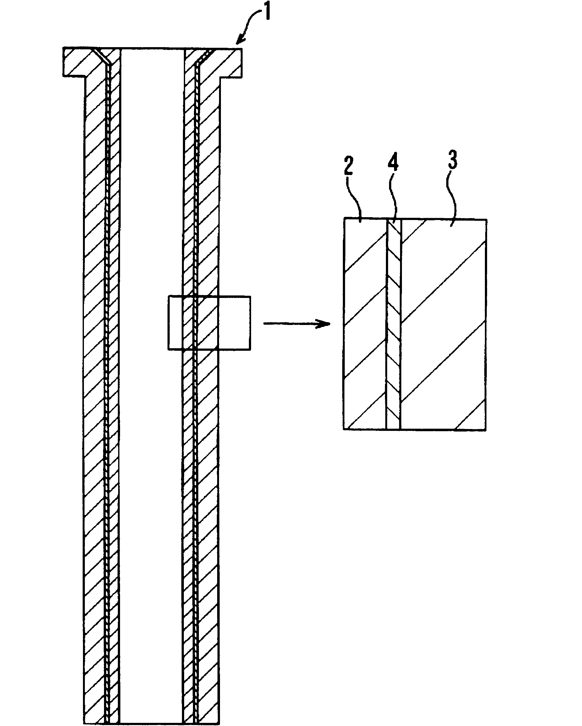
[0178] Such as figure 1 As shown, regarding the material arrangement structure of the long pouring nozzle 1 (inner hole diameter: Φ140mm, outer diameter of the straight shell part: Φ226mm, length 1500mm), as the inner hole side layer 2, a thickness of 10mm is used on all inner hole surfaces MgO-C material (MgO = 77% by mass, C = 19% by mass) with a maximum thermal expansion rate before 1500°C of 1.8% is arranged as the outer peripheral side layer 3 on the part not immersed in molten steel (non-impregnated part side) , Al with a maximum thermal expansion rate of 0.5% before 1500°C is arranged in a thickness of 30 mm 2 o 3 -SiO 2 -C material (Al 2 o 3 =50% by mass, SiO 2 =25% by mass, C=25% by mass), the thickness of the intermediate layer 4 for alleviating the thermal expansion of the inner hol...

Embodiment 7

[0197] In Example 7 and Example 8, a part of the combustible particles were replaced with fire-resistant particles. Sufficient shrinkability and adhesiveness were obtained, and good results were obtained. In Comparative Example 7, although the refractory particles were further increased compared with Example 7, sufficient shrinkability was not obtained, shrinkage cracks were observed in the intermediate layer, and sufficient adhesive strength was not obtained. As a result, even in the pouring test, peeling of the inner hole side layer occurred in the second time.

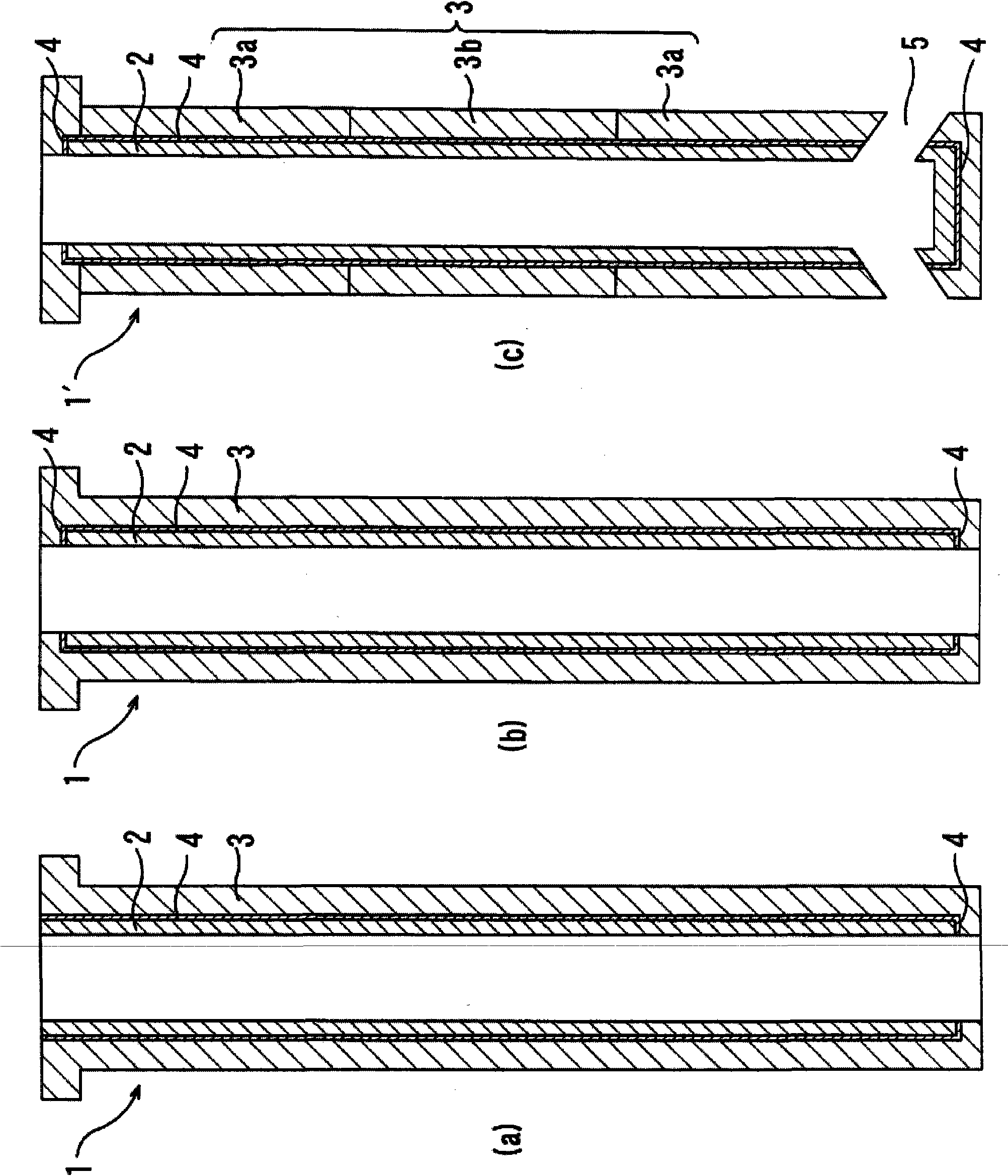
[0198] Above embodiment is that the present invention is applied to figure 1 example of a long sprue is shown, but is not limited to it, for example can also be applied to figure 2 The tubular refractory structure shown.

[0199] figure 2 Examples of (a), (b) are applied with figure 1 Example of the same long pouring tip, however, figure 2 In the example of (a), the refractory material of the outer layer ...


PUM

PropertyMeasurementUnit
tensile strengthaaaaaaaaaa
thicknessaaaaaaaaaa
thicknessaaaaaaaaaa

Abstract

A nozzle for continuous casting in which durability is enhanced by arranging a refractory layer of high performance, e.g. high corrosion resistance or high adhesion preventive properties, on the inner hole side. A method for manufacturing a nozzle for continuous casting in which push breaking of the outer circumferential side layer due to the difference in thermal expansion between the inner hole side layer and the outer circumferential side layer of body material is prevented, and exfoliation of the inner hole side layer in the way of casting is prevented, is also provided. The nozzle for continuous casting has such an integral structure as the boundary portion of the inner hole side layer (2) and an intermediate layer (4) touches the boundary portion of the intermediate layer (4) and the outer circumferential side layer (3) directly wherein the bonding strength of the intermediate layer and the inner hole side layer and the outer circumferential side layer adjoining the intermediate layer is 0.01-1.5 Mpa in a 1000 DEG C non-oxidizing atmosphere, and a compression rate K(%) of the intermediate layer in the 1000 DEG C non-oxidizing atmosphere under the pressure of 2.5 Mpa is 10%-80%.

Description

technical field [0001] The present invention relates to a pouring nozzle for continuous casting of molten metal, and more particularly to a tubular refractory structure having an inner hole through which molten metal passes in the axial direction, wherein a part or all of the tubular refractory structure has an inner hole Nozzles for continuous casting of side layers, middle layers, and peripheral side layers. [0002] In addition, the term "tubular" in the present invention refers to any shape having an inner hole in the axial direction regardless of the cross-sectional shape in a direction perpendicular to the axial direction. That is to say, the cross-sectional shape in the direction perpendicular to the axial direction is not limited to a circle, and may also be an ellipse, rectangle, polygon, and the like. [0003] In addition, the "inner hole side layer" in the present invention refers to a layer located in the inner side of the middle layer on a horizontal cross-sectio...

Claims


Application Information

Patent Timeline
Patent Type & Authority Applications(China)
IPC IPC(8): B22D11/10B22D41/50
CPCB22D41/50B22D41/52
Inventor 森川胜美佐佐木昭成波连孝一吉富丈记平岩义隆
Owner KROSAKI HARIMA CORP
Why Eureka
Try Eureka