Rotary writing method of multi-core fiber grating

A multi-core fiber, rotary technology, applied in the direction of multi-layer core/clad fiber, clad fiber, etc., can solve the problems of influence, small change of refractive index, and large difference of grating reflection peak.

Inactive Publication Date: 2010-09-08
HARBIN ENG UNIV
View PDF2 Cites 15 Cited by
  • Summary
  • Abstract
  • Description
  • Claims
  • Application Information

AI Technical Summary

Problems solved by technology

[0004] At present, both the theoretical analysis and the manufacturing process of single-core fiber gratings are quite mature, but most of the non-same-plane multi-core fiber gratings use one-side exposure technology [W.N.MacPherson, Meas.Sci.Technol.15, 1642, 2004 and the United States Patent No.20070201793A1], multiple core gratings are written at one time. The gratings produced by this preparation method have incon...

Method used


Image

  • Rotary writing method of multi-core fiber grating
  • Rotary writing method of multi-core fiber grating
  • Rotary writing method of multi-core fiber grating

Examples


Embodiment approach 1

[0025] refer to figure 2 Schematic diagram of the device used to manufacture multi-core fiber gratings in the present invention.

[0026] The embodiment of the manufacturing method of four-core fiber grating of the present invention specifically comprises the following steps:

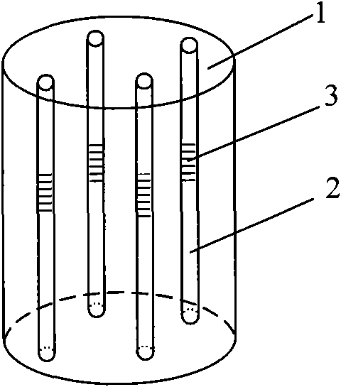
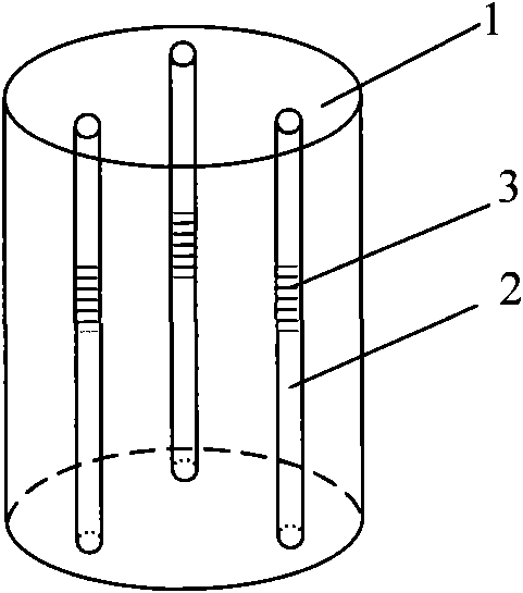
[0027] 1. Take a multi-core optical fiber 4, the optical fiber has four cores, and the four cores are symmetrically distributed on the concentric circle (as shown in Figure 3 (a)), strip the coating layer of the optical fiber with a length of 3-4cm, and clean it After processing, it is fixed on the optical fiber holder 9, and the position of each fiber core is observed with a microscope;

[0028] 2. Adjust the phase mask 8 to be close to the optical fiber, and adjust the multi-dimensional adjustment frame 10 to make the optical fiber and the phase mask 8 parallel to each other;

[0029] 3. Control and adjust the rotating optical device 11 by the stepping motor so that a certain fiber core of the optic...

Embodiment approach 2

[0035] The embodiment of the manufacturing method of dual-core fiber grating of the present invention specifically comprises the following steps:

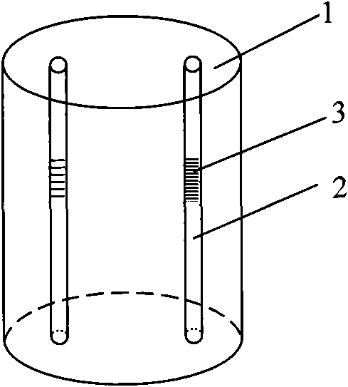
[0036] 1. Take a double-core optical fiber 4, peel off the coating layer of the optical fiber with a length of 3-4cm, and fix it on the optical fiber holder 9 after cleaning;

[0037] 2. Adjust the phase mask 8 to be close to the optical fiber, and adjust the multi-dimensional adjustment frame 10 to make the optical fiber and the phase mask 8 parallel to each other;

[0038] 3. Use a microscope to observe the position of each fiber core, and the stepping motor controls the rotating optical device 11 to adjust a certain fiber core of the fiber to face the phase mask 8, and fix it after adjustment;

[0039] 4. The ultraviolet light beam 5 is transformed into parallel light 7 through the ultraviolet beam collimation beam expansion system 6, and the phase is exposed on the optical fiber 4 through the mask plate 8;

[0040] 5. One end ...


PUM


Abstract

The invention provides a rotary writing method of a multi-core fiber grating, which comprises the following steps of stripping one section of coating on a multi-core fiber; fixing the multi-core fiber on a fiber fixture after cleaning treatment; arranging the fiber fixture on a rotary optical device; tightly attaching the multi-core fiber to a mask; regulating the rotary optical device so that one fiber core aligns with a writing optical source; starting an excimer laser, and conducting exposure after the optical source becomes parallel light through collimating and beam expanding; connecting one end of the multi-core fiber to a broadband optical source, and connecting the other end to a spectrograph; monitoring grating formation through the spectrograph, and stopping exposure after achieving the required reflectivity; regulating the rotary optical device to a proper angle so that the next fiber core of the multi-core fiber rightly aligns with the writing source for writing fiber by fiber; and packaging. The invention has the advantages of simple implementation and easy control, and can improve the writing quality of the grating; a plurality of manufactured multi-core fiber gratings are integrated in one fiber, which improves the integration of optical devices in the fiber and can be used for simultaneously measuring a plurality of physical quantities and multi-dimension information.

Description

technical field [0001] The invention belongs to the technical fields of optical fiber communication and optical fiber sensing, and relates to a manufacturing technology of a multi-core optical fiber grating. Background technique [0002] A typical optical fiber is a single-core structure, and the cladding surrounds the core to form a cylindrical optical waveguide. The multi-core optical fiber contains multiple cores in the same outer cladding, and each core is surrounded by a cladding material. Therefore, each fiber core is a fiber waveguide, that is, multiple single-core fibers are integrated in a multi-core fiber. The concept of multi-core optical fiber was proposed as early as the end of the 1970s. The purpose is to simultaneously solve the two major problems of reducing the manufacturing cost of optical fiber cables and developing high-density and large-core optical cables. However, it was not until the 1990s that with the continuous development and improvement of opti...

Claims


Application Information

Patent Timeline
IPC IPC(8): G02B6/036
Inventor 苑立波杨军关春颖
Owner HARBIN ENG UNIV
Why Eureka
Try Eureka