Photoelectrical coupling type terminal device

A terminal device and photoelectric coupling technology, which is applied in the direction of electrical components, electrical program control, electromagnetic wave transmission system, etc., can solve the problems of inability to realize information mutual access and integration, and the unification of fieldbus standards, so as to enhance the ability of network information exchange , reduce electromagnetic interference and electric shock and lightning damage, reduce the effect of hardware and software costs

Inactive Publication Date: 2010-09-15
HARBIN ENG UNIV
View PDF8 Cites 5 Cited by
  • Summary
  • Abstract
  • Description
  • Claims
  • Application Information

AI Technical Summary

Problems solved by technology

There are 19 kinds of fieldbus protocols in the current control field, but because the fieldbus has not yet achieved a unified standard, it is impossible to realize the truly transparent exchange of information from top (information management layer) to bottom (field device layer) in the integrated automation system of industrial enterprises. integrated

Method used


Image

  • Photoelectrical coupling type terminal device
  • Photoelectrical coupling type terminal device
  • Photoelectrical coupling type terminal device

Examples


example

[0030] Example: Use Ethernet to embed photoelectric coupling terminals to form a vehicle monitoring system.

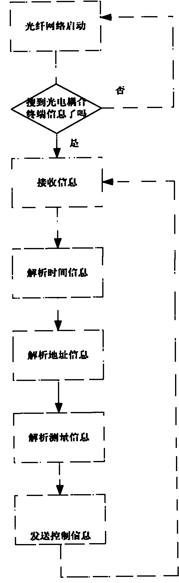
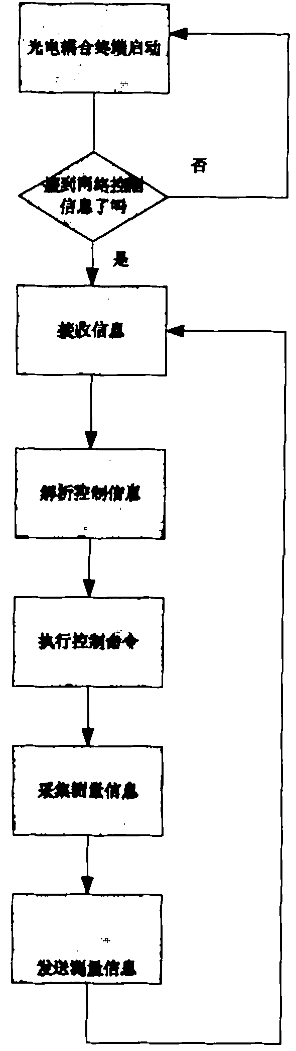
[0031] Due to the mobility of the car, the best information coupling system for monitoring the bus terminal is to use photoelectric coupling. The car has a photoelectric coupling terminal, as a node with an IP address, it can effectively receive and transmit measurement and control information and exchange information with the industrial measurement and control network during movement. Greatly improve the work efficiency of vehicle monitoring. Such as Figure 5 shown.

[0032] ①Equipment needs. One set of computer connected with industrial Ethernet, one set of car engine sensor, one set of car remote control sensor, one set of car mobile billing system, three photoelectric coupling terminals, one network reasoner with photoelectric transceiver, and one switch.

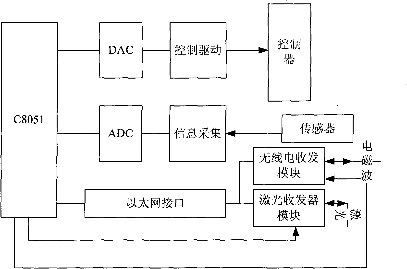
[0033] ②Network measurement and control terminal structure. The network control terminal is composed of...


PUM


Abstract

The invention relates to a photoelectrical coupling type terminal device characterized in that a terminal computer C8051 collects information through an ADC (Analog to Digital Converter) module, a wireless receiving and transmitting module and a laser transceiver module are used for communication through multi-frequency spectrum wireless photoelectrical signals and an optical network to transmit measuring information to a control center and then are used for communication through the multi-frequency spectrum wireless photoelectrical signals and the optical network to transmit the control information of the control center to the terminal computer C8051, and then the terminal computer C8051 inputs the information for control through a DAC (Digital-to-Analog Converter) module. The device can overcome the defects of coupling simplicity and immovability of the current terminal information and strengthen the exchange capacity of network information so that a bus can be measured and controlled through various kinds of media information to form a mobile network measuring and control bus.

Description

technical field [0001] The invention relates to an automation device, in particular to a new terminal device of an industrial control bus in the field of automation. Background technique [0002] The generation of networked control system comes directly from the development and wide application of computer control technology. In 1962, the British Imperial Chemical Industries Company pioneered the computer direct digital control system (DDC), but up to now, the on-site instruments and transmitters have not used computers as terminals; in terms of communication, advanced communication technology has not been used , Extending the backward 4-20mA analog signal and 232, 485 bus. From the structural point of view of current computer control, this kind of control system is too centralized and the field function is weak, so the centralized control system is increasingly unable to meet the actual needs of complex field information processing and communication. [0003] Honeywell la...

Claims


Application Information

Patent Timeline
Patent Type & Authority Applications(China)
IPC IPC(8): G05B19/418H04L12/24H04L12/28H04B10/12
CPCY02P90/02
Inventor 王克家王怡
Owner HARBIN ENG UNIV
Why Eureka
Try Eureka