Micro-fluid reactor, using method and application thereof

A microfluidic reactor and microreaction technology, applied in chemical instruments and methods, laboratory utensils, laboratory containers, etc., can solve the problems of complex system structure, cumbersome control, affecting the promotion and application of microfluidic reactors, etc. , to achieve the effect of simplifying the operation process, saving manpower and cost, and having a simple structure

Active Publication Date: 2010-10-06
SHANGHAI INST OF MICROSYSTEM & INFORMATION TECH CHINESE ACAD OF SCI
View PDF0 Cites 25 Cited by
  • Summary
  • Abstract
  • Description
  • Claims
  • Application Information

AI Technical Summary

Problems solved by technology

Although a lot of research has been done on microfluidic reactors at home and abroad, and many microfluidic reactor products have been developed, such as microfluidic reactors based on multiphase laminar flow mixing [Tokeshi M, Minagawa T, Uchiyama K, Hibara A , Sato K, Hisamoto H, Kitamori T. Continuous-flow chemical processing on a microchip by combining microunit operations and a multiphase flow network. Analytical Chemistry, 2002, 74(7): 1565-1571.] and droplet-based m

Method used


Image

  • Micro-fluid reactor, using method and application thereof
  • Micro-fluid reactor, using method and application thereof
  • Micro-fluid reactor, using method and application thereof

Examples


Embodiment 1

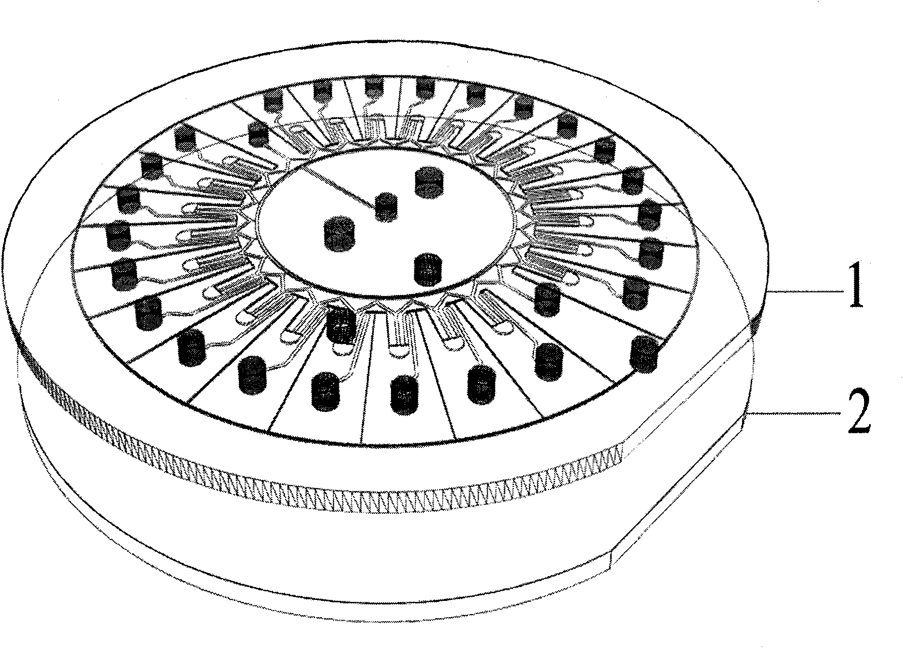
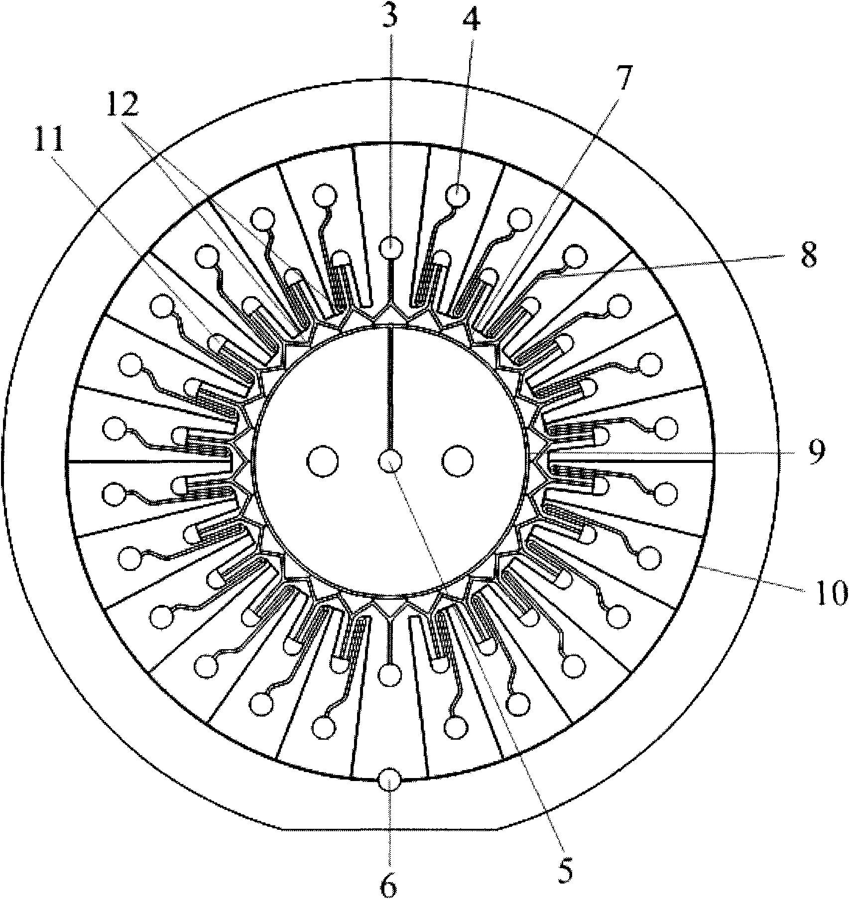
[0016] Such as figure 1 Shown, the microfluidic reactor of the present invention is a kind of composite disc-shaped microfluidic chip, and this chip is processed with microchannel and has the substrate 1 of hydrophobic property and the flat substrate of another surface with hydrophilic property by one surface 2 bonded structure; including main injection hole 3, branch injection hole 4, central ventilation hole 5, peripheral ventilation hole 6, main sampling micropipe 7, branch sampling micropipe 8, central ventilation micropipe 9, branch Structures such as ventilation micro-channel 10 and micro-reaction chamber 11 (such as figure 2 shown); wherein the cross-sectional aspect ratio of the main sampling micropipe 7 and the branch sampling micropipe 8 is greater than 1.5, ensuring that the hydrophilic force in the micropipe is greater than the hydrophobic force, so as to realize the microfluidic reactor based on capillary action At the same time, the micro-reaction chamber 11 wi...

Embodiment 2

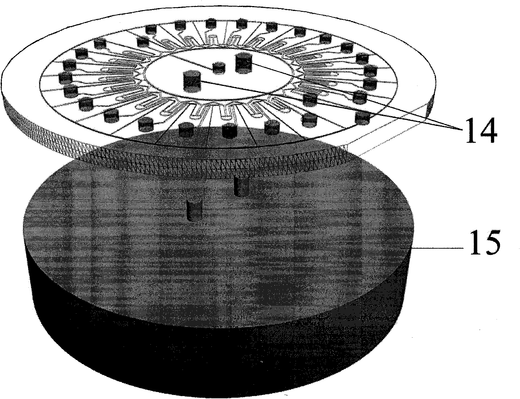
[0019] The microfluidic reactor prepared in Example 1 is applied to the high-throughput screening of protein crystallization conditions. The method is as follows: firstly, the protein solution to be crystallized is dropped into the main injection hole 3, and various crystallization ratios and concentrations The reagent is added to each branch sampling hole 4, and then the microfluidic reactor after the sampling is completed is placed and fixed on the centrifuge 15 through the chip fixing hole 14, and the chip is rotated at a high speed, and each section of the main sampling pipeline is separated by centrifugal force. The protein solution and the crystallization agent of each branch sampling pipeline are distributed to each micro-reaction chamber 11 for mixing, and then silicone oil is added into the central vent hole 5, and the microfluidic reaction is performed after the silicone oil fills the central vent pipe under the action of capillary force. The microfluidic reactor is c...


PUM


Abstract

The invention relates to an automatic high-pass micro-fluid reactor, a using method and application thereof. The micro-fluid reactor is a composite micro-fluid control chip constructed based on a surface hydrophilic material and a surface hydrophobic material, and comprises a plurality of radial micro tubes and micro cavities; and the micro-fluid reactor realizes automatic sample introduction of trace liquid samples in the micro tubes through a capillary acting force, and meanwhile realizes quantitative distribution and mixing of the trace samples by combining a capillary drain valve and a centrifugal force. The micro-fluid reactor can be applied to high-pass screening of chemical synthesis conditions and biochemical reaction conditions, and greatly saves manpower and cost. Compared with the conventional micro-fluid reactor, the micro-fluid reactor of the invention has a simple structure; and the using method does not need complex drive equipment and devices, simplifies the operation flow of the micro-fluid reactor, and is favorable for wide application of the micro-fluid reactor.

Description

technical field [0001] The invention relates to an automatic, high-throughput microfluidic reactor, a use method and an application thereof. The provided microfluidic reactor can be applied to the fields of chemistry, pharmacy and biology, especially for high-throughput screening of chemical synthesis and biochemical reaction conditions. Background technique [0002] "Microfluidic reactor" refers to a new type of miniaturized chemical reactor manufactured by micro-processing technology. In the past ten years, the application of microfluidic reactors has shown its advantages. It not only has the advantages of small space required, less sample consumption and fast response, but also has more environmental protection and safety characteristics than traditional equipment. Due to the reduction of the scale, in the microfluidic reactor, the surface volume ratio of the reaction system is greatly increased, the mass transfer path is extremely short, and the heat transfer speed is e...

Claims


Application Information

Patent Timeline
IPC IPC(8): B01J19/00B01L3/00
Inventor 李刚陈强李俊君赵建龙
Owner SHANGHAI INST OF MICROSYSTEM & INFORMATION TECH CHINESE ACAD OF SCI
Why Eureka
Try Eureka