
Process for the manufacture of rutile titanium dioxide powders

A technology of titanium dioxide and rutile, applied in the direction of titanium dioxide, titanium oxide/hydroxide, nanotechnology for materials and surface science, etc., can solve problems that are not rutile

Inactive Publication Date: 2010-10-13
UMICORE AG & CO KG
View PDF10 Cites 7 Cited by
  • Summary
  • Abstract
  • Description
  • Claims
  • Application Information

AI Technical Summary

Problems solved by technology

Titanium dioxide absorbs UV light efficiently, but it also tends to catalyze the formation of peroxides and hydroxyl radicals that can initiate unwanted oxidation reactions
Unfortunately, neither manganese nor chromium are effective rutile-promoting additives

Method used


Image

  • Process for the manufacture of rutile titanium dioxide powders
  • Process for the manufacture of rutile titanium dioxide powders

Examples


Embodiment 1

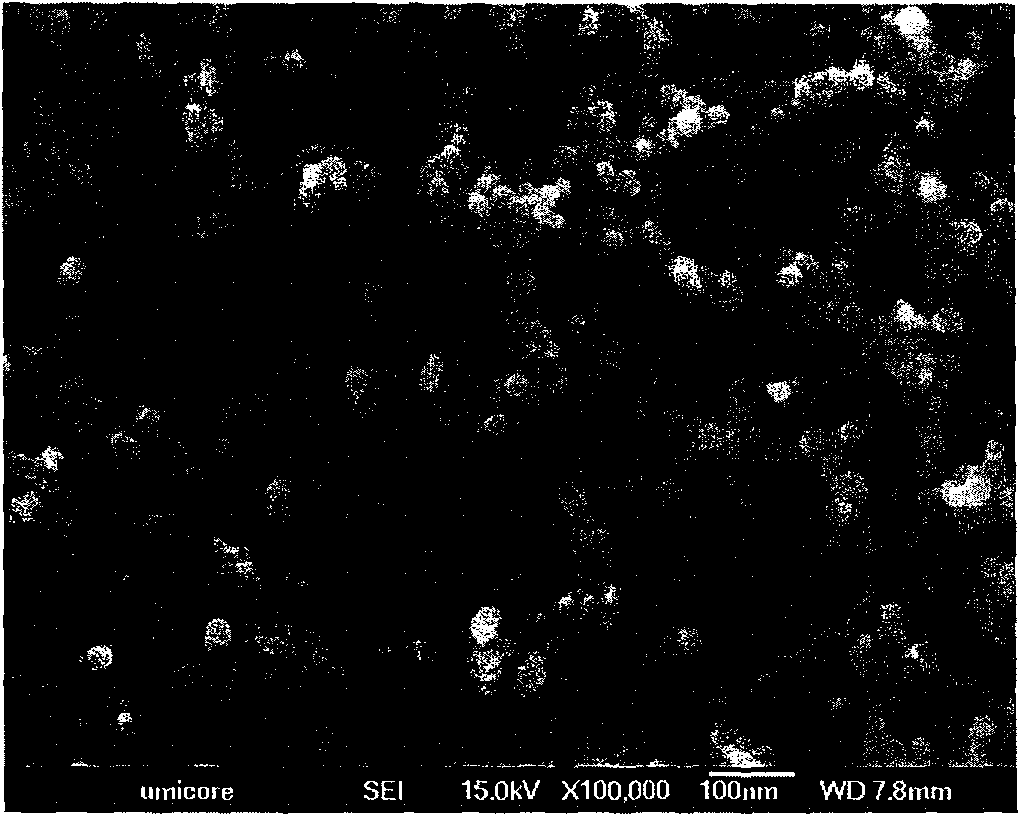
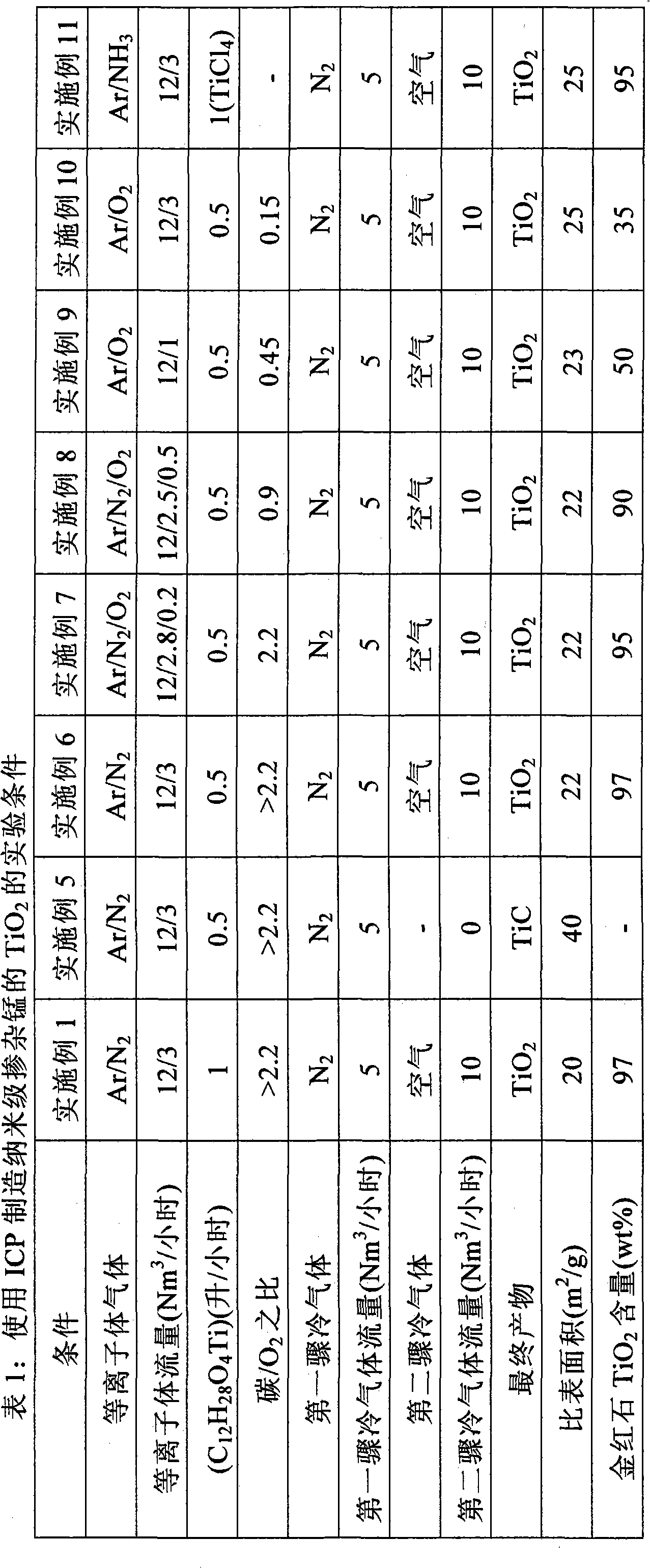
[0025] with 12Nm 3 / hr Argon and 3Nm 3 Argon / nitrogen plasma of nitrogen per hour, using a 25kW radio frequency (RF) inductively coupled plasma (ICP). The titanium isopropoxide is injected in the plasma at a flow rate of 1 liter / hour, resulting in a prevailing (i.e. in the reaction zone) temperature above 2000K in this first processing step, where the titanium isopropoxide is completely evaporated , so that it is easily nucleated to form cubic TiC nanopowders. 5Nm 3 A nitrogen flow per hour was used as the quench gas directly downstream of the reaction zone. This reduces the gas temperature to below 2000K. Furthermore, downstream, the 10Nm 3 Air per hour is blown into the airflow, thereby triggering a second processing step, which oxidizes the TiC powder to nanoscale rutile TiO 2 . Any residual carbon is also oxidized in this step. After filtration, nanoscale TiO is obtained 2 Powder with a rutile content of 97±2% and a specific surface area of ​​25±2m 2 / g. This co...

Embodiment 2

[0027] Under similar conditions, the apparatus of Example 1 was run. However, together with titanium isopropoxide, manganese isooctoate was injected into the plasma at a total injection flow rate of 1 liter / hour. After filtration, nanoscale manganese-doped TiO is obtained 2 Powder with a rutile content of 97±2% and a specific surface area of ​​25±2m 2 / g, the Mn content was 0.67±0.02%.

Embodiment 3

[0029] A 250kW direct current (DC) plasma torch was used with nitrogen as the plasma gas. The gas is at 150Nm 3 The plasma was discharged at a flow rate of / hour. A mixture of titanium isopropoxide and manganese isooctoate was injected downstream of the plasma at a flow rate of 25 kg / hour. In this step, the reactants were evaporated, resulting in a prevailing gas temperature of 2200K, and nucleated into Mn-doped TiC powder. Subsequently, in order to lower the gas temperature, 160Nm was applied 3 / hour nitrogen flow. Further downstream, at 6000Nm 3 Air is blown at a flow rate of / hour, thereby oxidizing TiC to nano-scale rutile TiO 2 . After filtration, a doped nanopowder was obtained with a rutile content of 97±2%, a Mn content of 0.67±0.02%, and a specific surface area of ​​18±2 m 2 / g, which corresponds to an average primary particle size of about 80 nm.


PUM


Abstract

This invention pertains to a process for producing ultra-fine rutile titanium dioxide powders. This particular compound is useful as UV-blocker in paints, plastics, coatings, pigments and sunscreens. The new process comprises the steps of providing a hot gas stream and of introducing therein firstly: - a titanium-bearing first reactant; and - a carbon- and / or nitrogen-bearing second reactant; the temperature of said gas stream being chosen so as to vaporize said first and second reactants, these being selected so as to form, at the prevalent temperature, titanium carbide, titanium nitride or a mixture thereof, as a nano-sized precursor; and, thereafter: - a volatile oxygen-bearing reactant selected so as to react with the nano-sized precursor, converting it to nano-sized titanium dioxide powder having a rutile content of at least 50%. This reaction scheme allows for the manufacture of powders with or without doping elements with a primary particle size between 1 and 100 nm.

Description

technical field [0001] The present invention relates to a method for producing ultrafine rutile titanium dioxide powder. Background technique [0002] Titanium dioxide can crystallize into three different forms, anatase, rutile, and brookite. Methods for producing ultrafine titanium dioxide powder include gas phase synthesis, colloidal precipitation and mechanical grinding. Important issues to be faced are the control of crystalline phase, particle size and distribution, degree of agglomeration and aggregation of particles, and degree of doping. [0003] During gas phase synthesis, by rapid quenching as described in US 5935293 and US 5851507, or using the method in US 5698117 and Akhtar et al., Dopants in Vapor-phase synthesis of titania, J 75 [12], 3408-16, 1992, low flame temperature and short residence time, enable control of TiO 2 particle size and distribution. EP 1514846 describes a method of eliminating oversized particles in the gas phase synthesis of metal oxide...

Claims


Application Information

Patent Timeline
IPC IPC(8): C01G23/07
CPCC01P2006/12C01G23/07C01P2004/64B82Y30/00
Inventor 斯特金·普特伊维斯·范罗姆帕伊
Owner UMICORE AG & CO KG
Learn More