Control system of pumping system

A control system and oil pumping technology, which is applied to the automatic control system of drilling, production fluid, drilling equipment, etc. It can solve the problems of low oil production cost, low system efficiency, very large power loss, and accelerated motor temperature rise.

Inactive Publication Date: 2014-07-09
杭州坤泽采油设备有限公司
View PDF7 Cites 0 Cited by
  • Summary
  • Abstract
  • Description
  • Claims
  • Application Information

AI Technical Summary

Problems solved by technology

[0004] Second, when it is matched with the submersible screw pump, the speed is too high to reduce the speed to the speed suitable for the screw pump through the tachometer. Even if the reducer is used, the cost of oil production will be greatly increased and the efficiency of the system will be reduced. The frequency conversion speed control device is used to keep the motor in a low-frequency working state for a long time, and it is easy to cause the temperature rise of the motor to accelerate, causing motor failure
[0005] Third, even if the traditional submersible electric pump system adopts frequency conversion control, its motor control cabinet is often placed on the ground. When the AC power is transmitted to the motor through long-distance transmission, the energy loss is serious, which further reduces the efficiency of the system.
[0007] In addition, since submersible motors are basically hundreds to thousands of meters underground, and existing submersible motors usually use AC motors, the three-phase AC power used by submersible motors will be transmitted from the ground to hundreds to several kilometers underground. Kilometers, therefore, the power loss in transmission is very large
However, the existing control system cannot solve this problem

Method used


Image

  • Control system of pumping system
  • Control system of pumping system
  • Control system of pumping system

Examples


no. 1 example

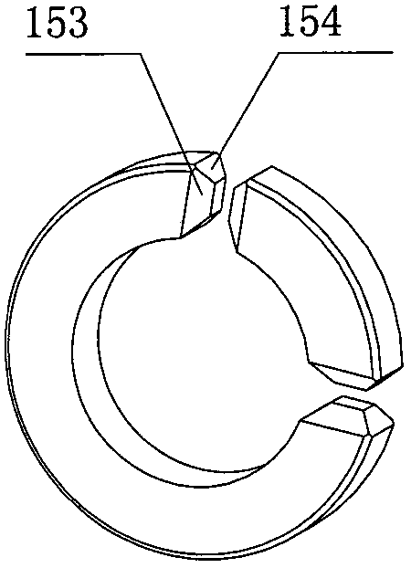
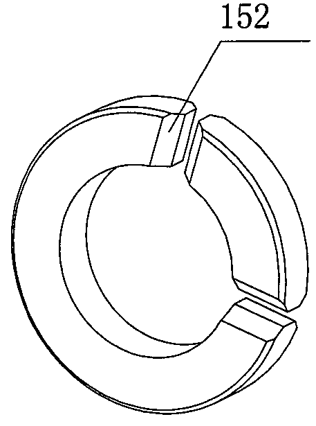
[0147] Figure 19 is an exploded schematic diagram of a magnetoelectric sensor solution equipped with two magnetic induction elements according to the first embodiment of the present invention. The magnetoelectric sensor includes inductive element 710, circuit board 711, magnetic conduction ring 712, stainless steel cover 713, magnetic steel ring 715 and casing (not shown), and magnetic steel ring 715 is installed on the motor tail shaft 716, and the rest It can be installed on the stainless steel cover 713 of the high-voltage threading sealing assembly 714 . The feature of this solution is that the magnetoelectric sensor has two magnetic induction elements, and the magnetic permeable ring 712 is also composed of two parts, one is a 1 / 4 magnetic ring, and the other is a 3 / 4 magnetic ring. Two incomplete magnetic rings form two slits for cooperating with two magnetic induction elements.

[0148] Figure 20 is a block diagram of a signal processing device of a magnetoelectric...

no. 2 example

[0198] In the second embodiment, there are two magnetic steel rings and two magnetic permeable rings, and there are correspondingly two columns of magnetic induction elements. These are the key components of the magnetoelectric sensor, and the installation and structure of other components are different from those of the other components. The similarities in the first embodiment are not repeated here.

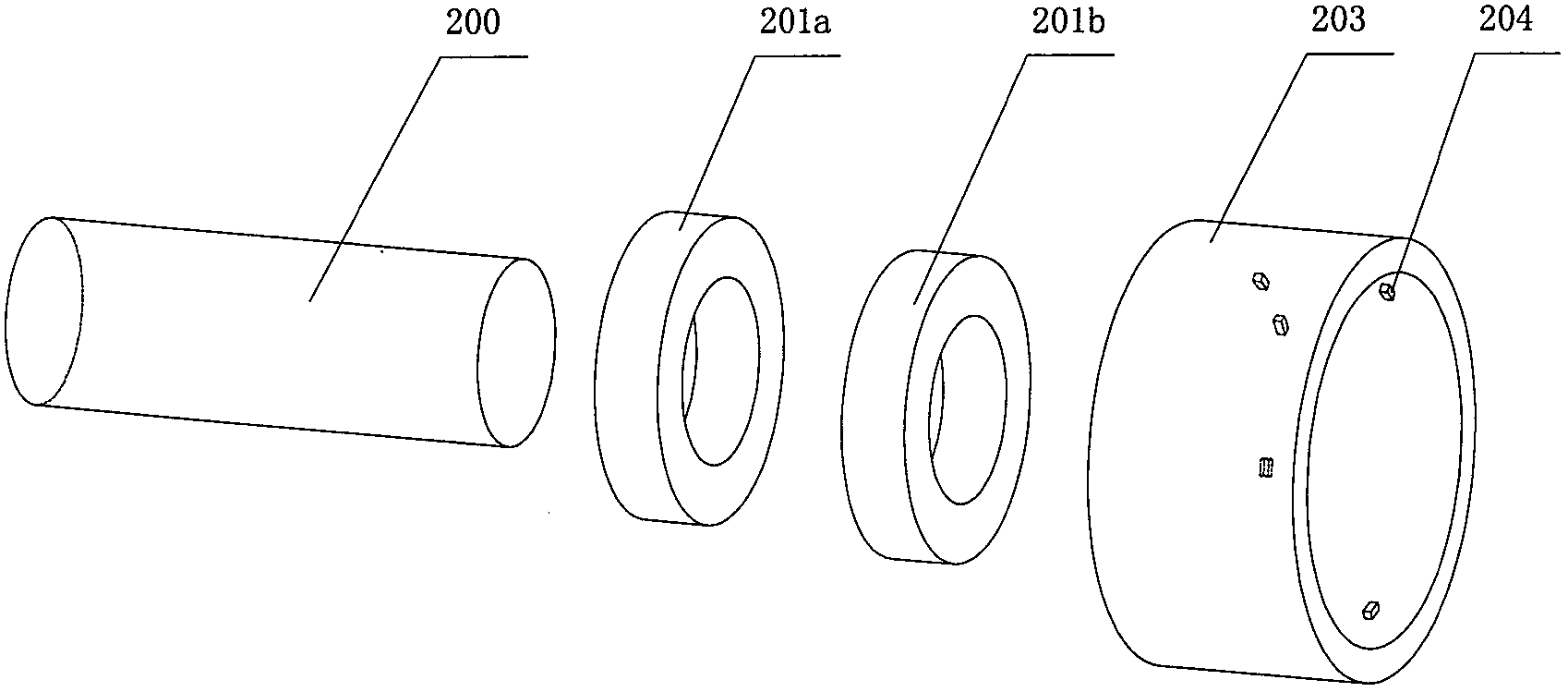
[0199] Figure 24 is an exploded perspective view of key components of the magnetoelectric sensor solution according to the second embodiment of the present invention. Figure 25 is a schematic diagram of the installation of the magnetoelectric sensor solution according to the second embodiment of the present invention. The magnetoelectric sensor of this embodiment includes a magnetic steel ring and a stator that wraps the magnetic steel ring inside. The magnetic steel ring includes a first magnetic steel ring 201a and a second magnetic steel ring 201b and a first magnetic per...

no. 3 example

[0223] In the third embodiment, the number of each component and its installation scheme are similar to those in the second embodiment, the difference is the magnetization method of the magnetic steel ring and the arrangement position of the magnetic induction element.

[0224] Figure 37 is an exploded perspective view of the magnetoelectric sensor according to the third embodiment. On the frame 306 , two rows of magnetic induction elements 307 are respectively arranged corresponding to the magnetic steel ring 302 and the magnetic steel ring 303 . Only one column of magnetic induction elements is shown in the figure. For the convenience of illustration, the first column of magnetic induction elements, that is, the multiple magnetic induction elements corresponding to the magnetic steel ring 302 and the magnetic permeable ring 304, are represented by magnetic induction elements 307, and the second column of magnetic induction elements That is, a plurality of magnetic inductio...


PUM


Abstract

The invention discloses a control system of an oil pumping system, which includes a servo motor located in the well, a motor control module and a sensor for collecting motor operation information; it also includes a power supply module and a ground control module located on the ground; the power supply module connects the ground The three-phase alternating current on the ground is converted into direct current and input to the downhole motor control module; the ground control module communicates with the motor control module, and sends user instructions and set parameters to the motor control module; the motor control module receives the The instructions and parameters sent by the ground control module and the information sent by the sensor are used to control the work of the servo motor. The invention avoids a large amount of energy loss during the long-distance transmission of alternating current, saves electricity consumption, improves transmission efficiency, and reduces equipment costs.

Description

technical field [0001] The invention relates to a control system, in particular to a control system applied to a downhole oil pumping system. Background technique [0002] At present, in my country and other oil-producing countries in the world, submersible motors are widely used in oilfields to drive submersible electric pumps to draw crude oil. The power source of traditional electric submersible pump systems is mainly two-pole three-phase asynchronous motors. The oil recovery system has the following problems in the matching of the oil recovery process: [0003] One is that when it is matched with the centrifugal submersible pump, because the motor speed is lower than the synchronous speed, the motor efficiency and power factor are low. [0004] Second, when it is matched with the submersible screw pump, the speed is too high to reduce the speed to the speed suitable for the screw pump through the tachometer. Even if the reducer is used, the cost of oil production will be...

Claims


Application Information

Patent Timeline
Patent Type & Authority Patents(China)
IPC IPC(8): E21B44/00
CPCE21B43/128E21B47/008
Inventor 郝双晖郝明晖
Owner 杭州坤泽采油设备有限公司
Why Eureka
Try Eureka