Built-in self-testing system and method thereof with mixed mode

A built-in self-test and mixed-mode technology, which is applied in the field of electronic equipment testing, can solve problems such as circuit thermal effects, increased test power consumption, and complex generation processes, achieving low test power consumption, reduced test power consumption, and high fault coverage Effect

Inactive Publication Date: 2010-11-10
NO 63908 TROOPS PLA
View PDF5 Cites 8 Cited by
  • Summary
  • Abstract
  • Description
  • Claims
  • Application Information

AI Technical Summary

Problems solved by technology

However, this pseudo-random test generation method also has many disadvantages: if a relatively high fault coverage rate is to be satisfied, the length of the generated test pattern generally needs to be very long, which greatly increases the test time and power consumption; there are a large number of random test patterns in the random test pattern. , The constantly changing bit code will greatly increase the power consumption of the test, resulting in the thermal effect of the circuit, which seriously affects the life of the device; in addition, the pseudo-random test pattern is mainly aimed at the fixed fault model, which cannot meet the requirements for delay, bridging, constant open circuit, etc. Test Requirements for Failure Types
But at the same time, there are also disadvantages such as complex generation process and difficult test application.

Method used


Image

  • Built-in self-testing system and method thereof with mixed mode
  • Built-in self-testing system and method thereof with mixed mode
  • Built-in self-testing system and method thereof with mixed mode

Examples


Embodiment 1

[0024] Embodiment 1 (the embodiment of the built-in self-test system of the present invention):

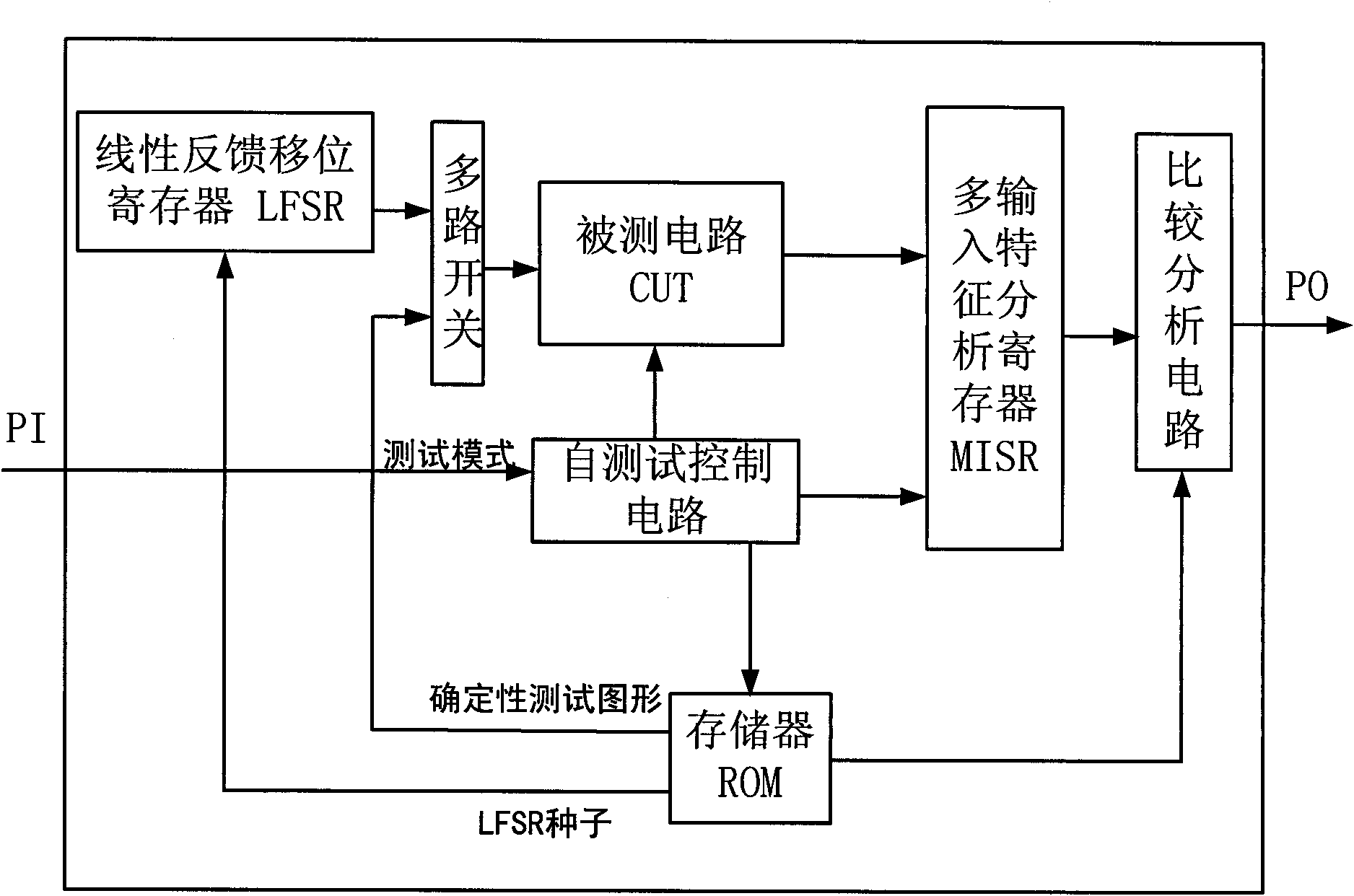
[0025] see figure 1 , a built-in self-test system of a mixed mode, comprising a circuit under test CUT, a self-test control circuit, a multi-input characteristic analysis register MISR, a memory ROM and a comparative analysis circuit; the self-test control circuit is respectively connected to the circuit under test CUT, The control terminal of the multi-input characteristic analysis register MISR and the memory ROM, the output terminal of the circuit under test CUT is connected to the input end of the multi-input characteristic analysis register MISR, and the input end of the comparison analysis circuit is respectively connected to the multi-input characteristic analysis register MISR Output terminal and the output terminal of memory ROM, PI is the signal input terminal of described self-test control circuit, PO is the signal output terminal of described comparative analysis circ...

Embodiment 2

[0026] Embodiment 2 (the embodiment of the built-in self-test method of the present invention):

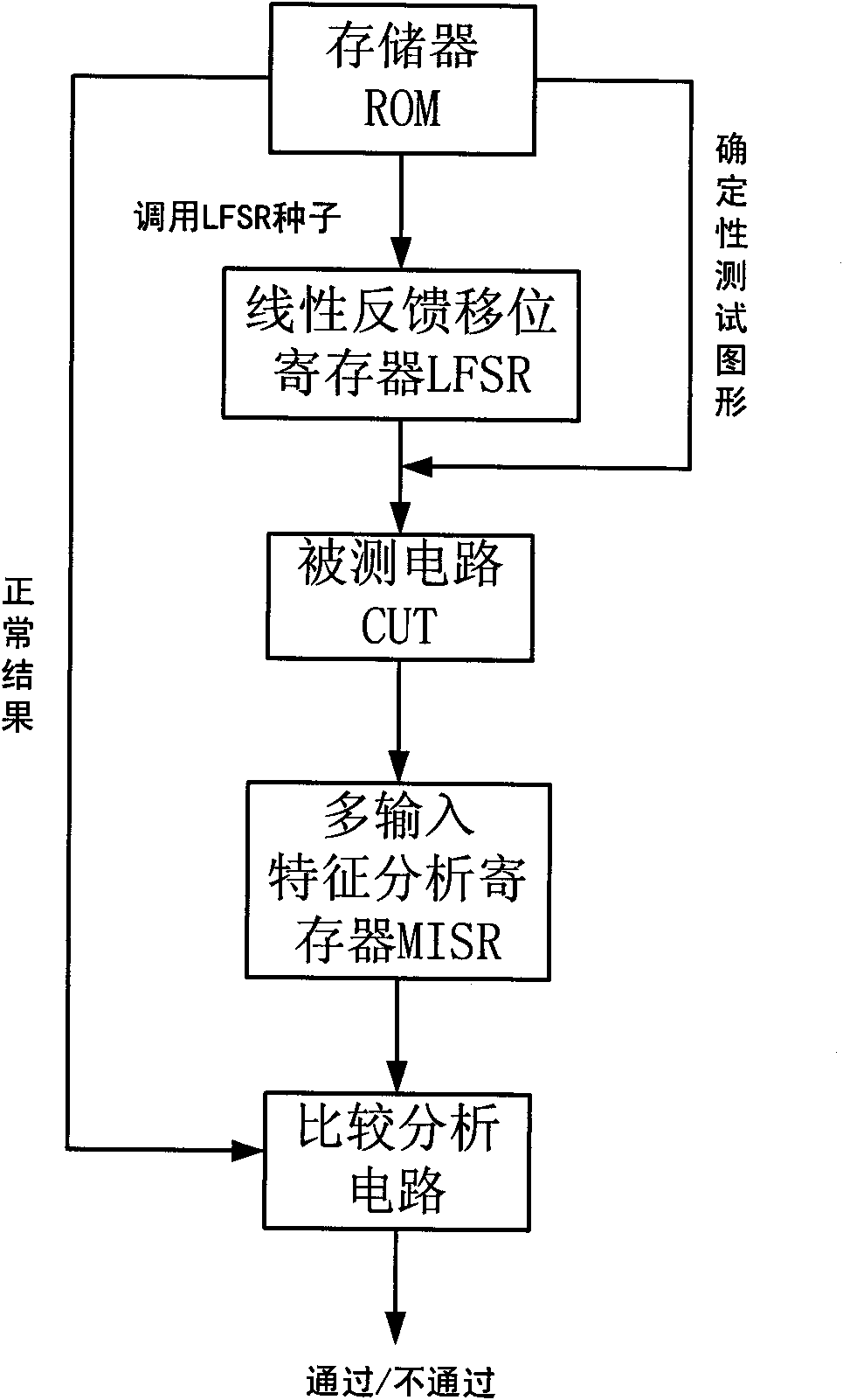
[0027] see figure 2 , a mixed-mode built-in self-test method. In the first step, the linear feedback shift register LFSR is selected as the test pattern generation circuit through a multi-way switch, and the required test pattern is generated after calling the seed stored in the memory ROM and then applied To the circuit under test CUT, its output response is analyzed by the multi-input characteristic analysis register MISR, and then compared with the characteristic response pre-stored in the memory ROM by the comparison analysis circuit, and a pass / fail result is given;

[0028] In the second step, the deterministic test pattern stored in the memory ROM is selected by a multi-way switch as the test pattern of the circuit under test CUT, and the output response of the circuit under test CUT is analyzed by the multi-input characteristic analysis register MISR and then analyzed by ...


PUM


Abstract

The invention relates to a built-in self-testing system and a method thereof with a mixed mode. The testing system comprises a circuit (CUT) to be tested, a self-testing control circuit, a multi-input feature analysis register (MISR), a memory (ROM) and a comparative analysis circuit. The invention has the improvement that the built-in self-testing system also comprises a linear feedback shift register (LFSR) which is used for generating a pseudo-random testing figure and a multi-way switch; the input end of the linear feedback shift register (LFSR) is connected with the memory (ROM), one input end of the multi-way switch is connected with the output end of the linear feedback shift register (LFSR), the other input end of the multi-way switch is connected with the memory (ROM), and the output end of the multi-way switch is connected to the input end of the circuit (CUT) to be tested; and the testing method of the built-in self-testing system is a built-in self-testing method which is based on a pseudo-random method and a determinacy generation method and has a mixed mode. The invention has the advantage that the self-testing system and the method thereof have high fault-coverage rate, short testing time, low testing power consumption and simple structure.

Description

technical field [0001] The invention relates to the technical field of electronic equipment testing, in particular to a mixed-mode built-in self-testing system and a method thereof. Background technique [0002] Testability design mainly refers to the need to fully consider the test problem when designing the circuit, so that the device itself has the design characteristics of self-testing and providing convenience for diagnosis. With the increasing complexity of integrated circuit design, traditional automatic test equipment (ATE) can no longer meet the needs of integrated circuit testing. Adding test circuits in the circuit design process to reduce the difficulty of chip test test design technology can significantly improve the fault coverage of the test, shorten the time to market of the chip, and reduce the dependence of test equipment on ATE equipment. Test design technology has become a solution Chip testing problems and the main means of reducing the cost of testing....

Claims


Application Information

Patent Timeline
Patent Type & Authority Applications(China)
IPC IPC(8): G01R31/3185
Inventor 连光耀黄考利葛鹏岳孙江生王振生刘彦宏吕晓明王韶光王凯张延生
Owner NO 63908 TROOPS PLA
Why Eureka
Try Eureka