Infrared window protective film material, use thereof and preparation method thereof

A technology of infrared window and infrared optical window, applied in the field of infrared optical thin film, can solve the problems of large film stress, harsh deposition conditions of diamond film, preparation of diamond protective film, etc., and achieve the effect of good performance and good application prospect.

Inactive Publication Date: 2010-11-17
UNIV OF SCI & TECH BEIJING
View PDF7 Cites 4 Cited by
  • Summary
  • Abstract
  • Description
  • Claims
  • Application Information

AI Technical Summary

Problems solved by technology

As the protective film of ZnS and ZnSe windows, diamond-like film and Ge-C film have certain hardness, but the stress of this film is too large, so it is difficult to coat thicker diamond-like film on ZnS and ZnSe window , so the diamond-like film has a limited protective effect on ZnS and ZnSe windows (Waddell, Ewan M; Gibson, Desmond R; Meredith, J. Proceedings of SPIE-The International Society for Optical Engineering, v 2286, p 364-375, 1994)
The diamond film itself has extremely high hardness and is considered to be the best protective film material for the infrared window. However, the deposition c

Method used


Image

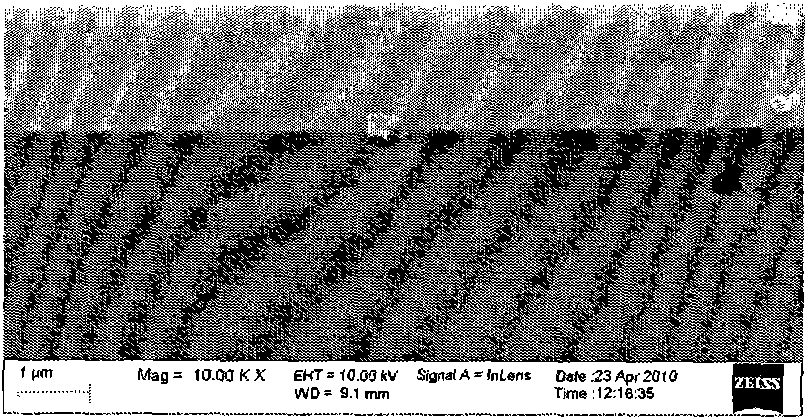
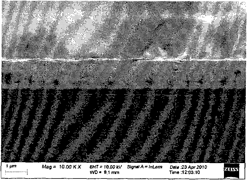
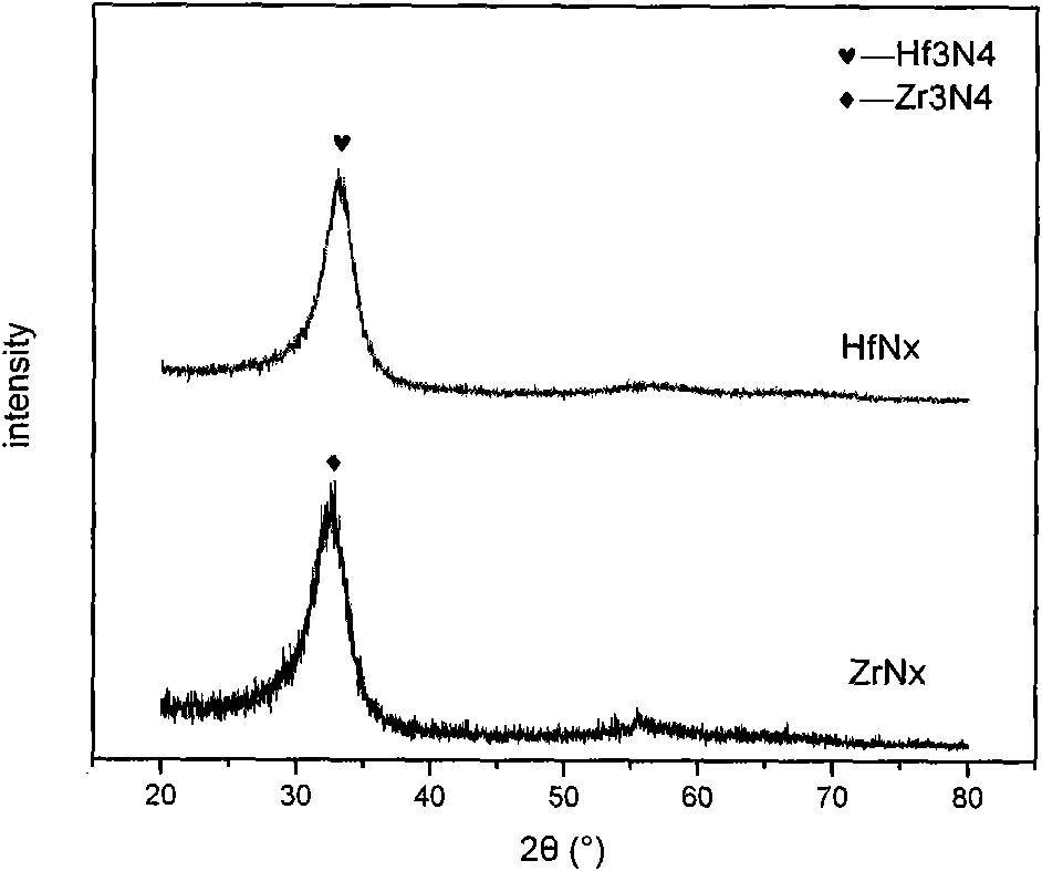
  • Infrared window protective film material, use thereof and preparation method thereof
  • Infrared window protective film material, use thereof and preparation method thereof
  • Infrared window protective film material, use thereof and preparation method thereof

Examples


Example Embodiment

[0025] Example 1

[0026] 1. Select the sputtering method of physical vapor deposition method to prepare the required (Zr, Hf)Nx nitride film.

[0027] 2. The reaction chamber is evacuated to below 6×10^-3Pa, the substrate heater is turned on during the vacuuming process, the temperature is set to 300℃, argon gas is introduced, the flow rate is 8.0sccm, and the reaction chamber pressure is 0.50~ 0.54Pa, turn on the RF power supply, adjust the substrate bias voltage to -300V, and perform pre-sputtering for 20 minutes. During this process, the target and the target are separated by a baffle.

[0028] 3. After pre-sputtering, turn off the substrate power supply, adjust the argon gas flow to 2.5sccm, open the nitrogen flow valve, adjust the nitrogen flow so that the N2 / Ar flow ratio is 0.72, and adjust the target power supply to set the input power to 100~300W. Remove the baffle and start deposition, the deposition pressure is 0.34-0.41 Pa, and the deposition time is 60 minutes.

[0029]...

Example Embodiment

[0039] Example 2

[0040] 1. Select plasma-assisted chemical vapor deposition method to prepare the required (Zr, Hf)Nx nitride film.

[0041] 2. Evacuate the reaction chamber to below 6×10^-3Pa, turn on the substrate heater during the evacuation process, set its temperature to 500°C, and etch with Ar for 5 minutes, and the flow rate of Ar is 10sccm. The chamber pressure is 5000±100Pa.

[0042] 3. Turn off the Ar flowmeter after etching, vacuum again to below 6×10^-3Pa, and pass in ammonia gas and Zr tetrachloride or Hf tetrachloride with flow rates of 25 sccm and 5 sccm respectively. Adjust the pressure in the reaction chamber to 5000Pa, turn on the RF power supply, adjust the power to 500W, and start the chemical vapor deposition of (Zr, Hf) nitride film. During the deposition process, the gas flow rate is kept constant, the pressure of the reaction chamber is kept between 5000±100Pa, and the deposition time is 60 minutes.

[0043] 4. After the deposition is completed, step-wise c...


PUM

PropertyMeasurementUnit
Hardness valueaaaaaaaaaa

Abstract

The invention belongs to the technical field of infrared optical thin films and particularly relates to novel transitional metal Zr and Hf nitride optical thin films, use thereof and a preparation method thereof. The infrared window protective film material consists of transitional metal Zr and Hf nitrides and can be expressed as (Zr, Hf)Nx, wherein x represents the nitrogen content; and the value of the x ranges from 1.0 to 1.5. The material is particularly suitable to be used for manufacturing far-infrared band ZnS and ZnSe infrared window protective films which have high transmissivity, high hardness and low internal stress. The films can be made by various methods such as physical gas-phase deposition or chemical gas-phase deposition and have a promising prospect.

Description

technical field [0001] The invention belongs to the technical field of infrared optical thin films, and in particular relates to a novel transition metal Zr, Hf nitride optical thin film, its application and its preparation method. Background technique [0002] The types of optical materials that can be applied in the 8-12 μm far-infrared band are extremely limited, and among the limited materials, ZnS and ZnSe are the two most widely used materials. ZnS and ZnSe have good optical properties in the 8-12 μm band, but they also have significant disadvantages. Among them, the extremely low hardness makes ZnS and ZnSe easy to be scratched in the application, resulting in their optical windows. failure. [0003] So far, people have studied a variety of ZnS, ZnSe protective layer materials, including diamond-like film and Ge-C film, PB film and diamond film and so on. As the protective film of ZnS and ZnSe windows, diamond-like film and Ge-C film have certain hardness, but the s...

Claims


Application Information

Patent Timeline
IPC IPC(8): G02B1/10C23C14/35C23C14/06C23C16/34C23C16/455G02B1/14
Inventor 唐伟忠许恒志惠大胜
Owner UNIV OF SCI & TECH BEIJING
Why Eureka
Try Eureka