Intelligent electronic spot welder and spot welding method thereof

An electronic point and intelligent technology, applied in the direction of resistance welding equipment, welding power supply, electrode characteristics, etc., can solve the problems of small solder joint thickness, large solder joint thickness, low temperature resistance and low temperature resistance of solder joints, etc., and achieve easy use , high degree of automation, solve the effect of virtual welding and disconnection

Active Publication Date: 2010-11-24
珠海精易焊接设备有限公司
View PDF5 Cites 14 Cited by
  • Summary
  • Abstract
  • Description
  • Claims
  • Application Information

AI Technical Summary

Problems solved by technology

Although the electronic spot welding machines in the past are also micro spot welding, they also have a host, a plate frame and a pressure device, but they are all foot-operated manual spot welding equipment, which has serious defects in the welding process of electronic components. , that is, only welding without detecting the welding quality of solder joints
In the case of certain welding parameters in this operation mode, the quality of the solder joints mainly depends on the thickness of the solder joints. If the welding pressure of the pedal is too small, the thickness of the solder joints will be too large, and the contact surface of the solder joints will not form an alloy surface, thus It causes the virtual welding phenomenon of the solder joints, which reduces the high temperature and low temperature resistance of the solder joints, and leads to the unreliability of electronic components.
If the welding pressure of the foot pedal is too high, the thickness of the solder joints will be too small, which will cause the enameled wires of the solder joints to break, which is an increasingly serious problem in the production of electronic components in the aerospace industry and advanced medical equipment industry.

Method used


Image

  • Intelligent electronic spot welder and spot welding method thereof
  • Intelligent electronic spot welder and spot welding method thereof
  • Intelligent electronic spot welder and spot welding method thereof

Examples


Embodiment 1

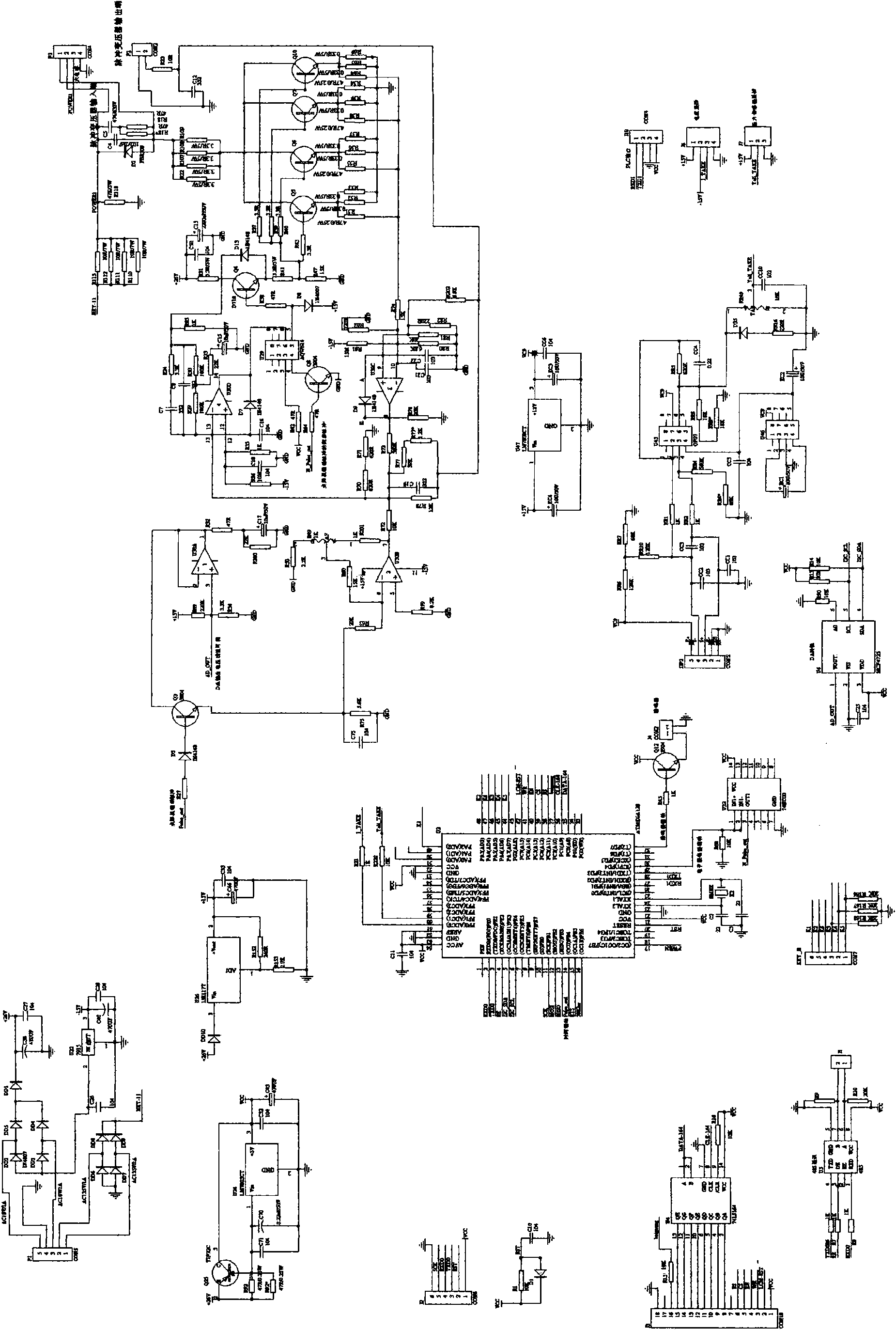
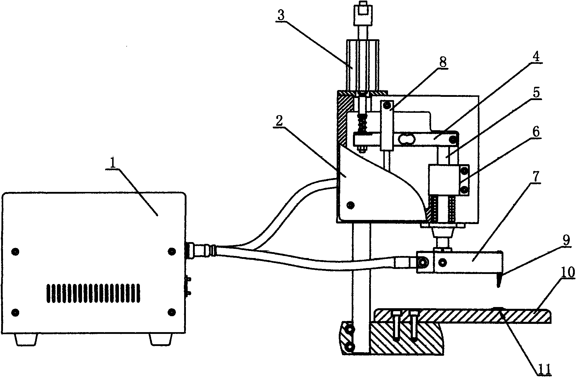
[0048] Embodiment one: if Figure 1 to Figure 3 As shown, the intelligent electronic spot welding machine of the present invention comprises a main frame 1, a head 2 and a cylinder 3. The main frame 1 is provided with a single-chip microcomputer control circuit and a welding parameter database management program, and the connecting rod provided with the cylinder 3 and the rear end of the pressure sensor 4 Connected, an electronic grating scale 8 is installed above the pressure sensor 4, the front end of the pressure sensor 4 is linked with the front axle 5, the middle part of the front axle 5 is equipped with an electromagnetic brake device 6, and the welding head clamp 7 is installed at the lower end of the front axle 5, The front end of the welding head clamp 7 is fixed with a spot welding head 9, and below the spot welding head 9 are a workbench 10 and a workpiece 11 to be welded.

[0049] The host 1 controls the cylinder 3, the pressure sensor 4, the electromagnetic brakin...

Embodiment 2

[0050] Embodiment two: if figure 1 , figure 2 and Figure 4 As shown, the intelligent electronic spot welding machine of the present invention comprises a main frame 1, a head 2 and a servo motor 12. The main frame 1 is provided with a single-chip microcomputer control circuit and a welding parameter database management program. The main shaft of 12 is connected to the rear end of the pressure sensor 4 through the flange, and the front end of the pressure sensor 4 is connected to the front shaft 5, and the lower end of the front shaft 5 is equipped with a welding head clamp 7, and the front end of the welding head clamp 7 is fixed with a spot welding head 9, There are 2,000 kinds of welding parameters stored in the memory chip of the host 1, and the paint removal pulse, welding pulse and repair welding pulse are output according to the detected data, and the measurement, welding voltage, current and welding pressure are displayed in real time through the liquid crystal displ...


PUM


Abstract

The invention relates to an intelligent electronic spot welder and a spot welding method thereof. The spot welder comprises a host machine provided with a singlechip and a welding database, and a machine head; the machine head comprises a driving device, a front shaft and a welding head; and a detector and a braking device are respectively connected with the front shaft. The detector transmits the acquired data to the singlechip so as to make the welding head automatically perform welding action through the host machine. The intelligent electronic spot welding method comprises the following steps of: (1) establishing a welding parameter database; (2) measuring the diameter of an enameled wire to be processed; (3) outputting a paint-removing pulse for paint removal; (4) outputting a welding pulse for welding; (5) and measuring or performing repair welding. The Intelligent electronic spot welder has real-time detection and repair welding function, namely synchronously welds and detects welding spot quality, and detects a welding spot once the welding spot is welded to form a closed-loop automatic detection system, solves the problems of no detection of the welding spot quality afterwelding, and insufficient welding and wire break during spot welding of the conventional spot welder, and improves the reliability of processing electronic components in the industries of communication, aviation and aerospace and advanced medical equipment.

Description

technical field [0001] The invention relates to an electronic spot welding machine and an electronic spot welding method, in particular to an intelligent electronic spot welding machine and a spot welding method specially used in the electronics industry, precision instruments and microelectronics industry. Background technique [0002] At present, with the rapid development of electronic components in the communication industry, aerospace industry and advanced medical equipment industry, people have put forward higher requirements for the production and production of electronic components, especially for micro spot welding of electronic components. skills requirement. Although the electronic spot welding machines in the past are also micro spot welding, they also have a host, a plate frame and a pressure device, but they are all foot-operated manual spot welding equipment, which has serious defects in the welding process of electronic components. , that is, only welding wi...

Claims


Application Information

Patent Timeline
Patent Type & Authority Applications(China)
IPC IPC(8): B23K11/11B23K11/24B23K11/25B23K11/30
Inventor 陈利生黎原
Owner 珠海精易焊接设备有限公司
Why Eureka
Try Eureka