
Ceramic particle reinforced composite wear-resistant part and preparation method thereof

A technology of reinforced composite and ceramic particles, which is applied in the field of hammer heads of crushers, and can solve problems affecting the quality of castings, difficult penetration of molten metal, fracture or peeling of composite materials, etc.

Inactive Publication Date: 2012-03-28
XI AN JIAOTONG UNIV +1
View PDF5 Cites 1 Cited by
  • Summary
  • Abstract
  • Description
  • Claims
  • Application Information

AI Technical Summary

Problems solved by technology

[0005] Although this is a better solution, there are still some problems in previous inventions and researches: ①WC, SiC, Cr 3 C 2 Although these particles have good wettability with high-temperature molten iron and are easier to cast and infiltrate, the ceramic particles themselves are more expensive and the cost is higher; ② Whether it is cast infiltration method or self-propagating method, binders should be used in the preparation of particles, which will easily cause outgassing during casting and affect the quality of the casting; A composite material with high hardness and high wear resistance, but its toughness decreases and brittleness increases. If the entire layer of composite material covers the surface of wear-resistant parts, the hard and brittle composite material may break or peel off in advance under impact conditions.
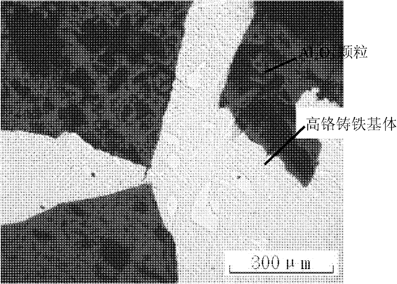
However, there are also difficulties in the preparation of composite materials by using oxide ceramics: oxide ceramics and iron do not infiltrate, it is difficult for molten metal to penetrate the particle preform, and the casting penetration depth is limited

Method used


Image

  • Ceramic particle reinforced composite wear-resistant part and preparation method thereof
  • Ceramic particle reinforced composite wear-resistant part and preparation method thereof
  • Ceramic particle reinforced composite wear-resistant part and preparation method thereof

Examples


Embodiment 1

[0027] Example 1: hammer crusher hammer

[0028] 1) First, mix alumina ceramic particles with a particle size of 8-60 mesh and high-manganese steel metal powder with a particle size of 150-400 mesh with absolute ethanol to obtain a mixture, wherein the mass ratio of oxide ceramic particles to metal powder 1:0.8, the addition of absolute ethanol is 3% of the oxide ceramic particles;

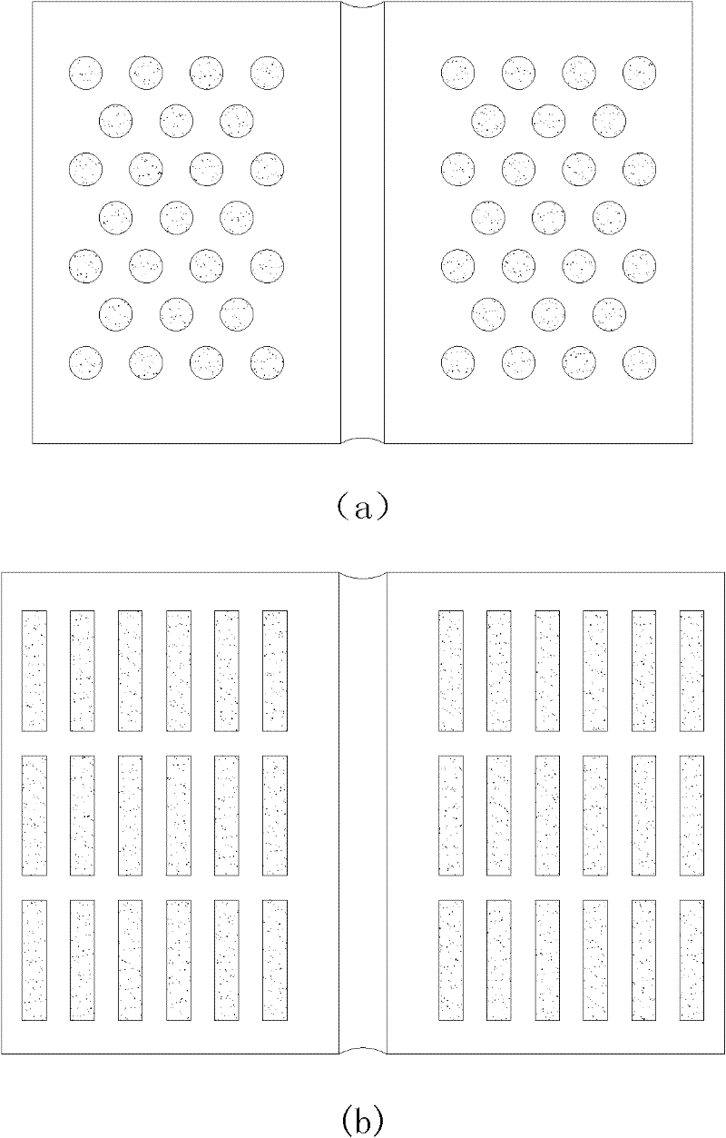
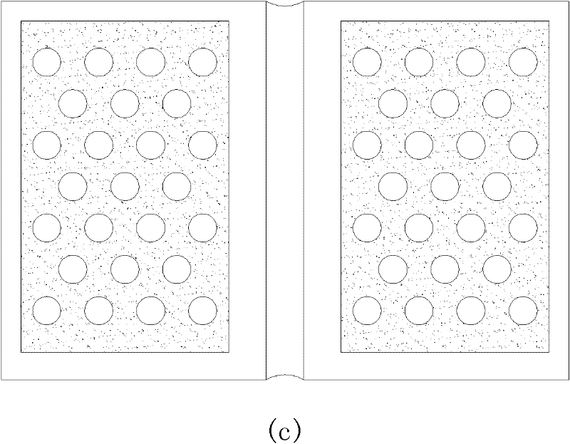
[0029] 2) Then, fill the mixture into a columnar, strip-shaped or honeycomb graphite mold. In order to prevent the mold from sticking, a layer of graphite paper with a thickness of 0.4-0.6mm is placed between the mixed particles and the mold, and dried at 80°C The mixture is mixed particles, and then the mold and the mixed particles are put into a vacuum sintering furnace for sintering at 1300 ° C and a vacuum degree of 0.1 Pa for 45 minutes, and the metal powder bonds the ceramic particles together to form a prefabricated body;

[0030] 3) After cooling, open the mold, take out the sintered pref...

Embodiment 2

[0032] Example 2: hammer crusher hammer head

[0033] 1) First, uniformly mix zirconia ceramic particles with a particle size of 8-60 mesh and alloy steel metal powder with a particle size of 150-400 mesh with absolute ethanol to obtain a mixture, wherein the mass ratio of the oxide ceramic particles to the metal powder is 1:0.5, the addition of absolute ethanol is 4% of the oxide ceramic particles;

[0034]2) Then, the mixture is filled in a block graphite mould. In order to prevent the mold from sticking, a layer of graphite paper with a thickness of 0.4 to 0.6mm is placed between the mixed particles and the mold, and the mixture is dried at 80°C to obtain the mixed particles, and then Put the mold together with the mixed particles into the vacuum sintering furnace and sinter for 50 minutes at 1280°C and a vacuum of 0.1 Pa. The metal powder bonds the ceramic particles together to form a prefabricated body;

[0035] 3) After cooling, open the mold, take out the sintered pref...

Embodiment 3

[0037] Embodiment 3: vertical cement grinding roller

[0038] 1) First, mix alumina ceramic particles with a particle size of 8-60 mesh and high-manganese steel metal powder with a particle size of 150-400 mesh with absolute ethanol to obtain a mixture, wherein the mass ratio of oxide ceramic particles to metal powder 1:1.5, the addition of absolute ethanol is 4.2% of the oxide ceramic particles;

[0039] 2) Then, the mixture is filled in a honeycomb graphite mould. In order to prevent sticking to the mould, a layer of graphite paper with a thickness of 0.4 to 0.6mm is placed between the mixed particles and the mold, and the mixture is dried at 80°C to obtain the mixed particles, and then Put the mold together with the mixed particles into a vacuum sintering furnace and sinter for 30 minutes at 1350°C and a vacuum of 0.1 Pa. The metal powder bonds the ceramic particles together to form a prefabricated body;

[0040] 3) After cooling, open the mold, take out the sintered prefa...


PUM

PropertyMeasurementUnit
particle size (mesh)aaaaaaaaaa
thicknessaaaaaaaaaa
hardnessaaaaaaaaaa

Abstract

The invention relates to a ceramic particle reinforced composite wear-resistant part and a preparation method thereof. The method comprises the following steps: ceramic particles and metal powder are mixed evenly to fill in a special mould; then the mixture along with the mould is placed in a vacuum sintering furnace to sinter, wherein metal powder and ceramic particles are bound together to forma perform; after cooled, the mould is opened to take the perform out and place the perform on the side of the end face of a casting mold cavity; parent metal material is smelted by a medium-frequency induction furnace to form molten metal; during the casting, the molten metal is poured, metal powder in the perform is molten to form a cast-penetration path under the heat of molten metal, thus the molten metal can easily penetrate ceramic particles to form particle reinforced composite material in situ; and the surface layer of the obtained wear-resistant part consists of parent metal and composite material. The wear resistance of the composite material prepared by the method of the invention is ensured and the composite material has high impact resistance.

Description

technical field [0001] The invention relates to a ceramic particle reinforced composite wear-resistant part and a manufacturing method thereof. It is especially suitable for hammer heads of crushers, blow bars, large cement grinding rollers and grinding discs, etc. Background technique [0002] Wearable parts used in grinding equipment and crushing equipment encountered in cement, mining, metallurgy, power station or various similar industries. These parts usually require good overall mechanical properties, and it is desirable that these parts not only have high wear resistance, but also have a certain degree of toughness, so as to have mechanical strength such as impact resistance and be able to be machined. As we all know, these properties are difficult to coordinate in the same material. In order to solve this contradiction, the use of composite materials is a better choice. [0003] Particle-reinforced composite materials have been widely studied and applied in recent ...

Claims


Application Information

Patent Timeline
Patent Type & Authority Patents(China)
IPC IPC(8): B22D19/02C22C29/00C22C32/00C22C1/05
Inventor 高义民史芳杰李林王娟李烨飞郑飞燕尹宏飞邢建东
Owner XI AN JIAOTONG UNIV
Learn More