Hybrid construction machine and control method of hybrid construction machine
A construction machinery and hybrid technology, which is applied in the control system, control device, control generator, etc., can solve the problems of driver damage, load control deviation, and large voltage value fluctuation of the storage mechanism, so as to suppress the voltage value change , the effect of suppressing deviation
- Summary
- Abstract
- Description
- Claims
- Application Information
AI Technical Summary
Problems solved by technology
Method used
Image
Examples
Embodiment approach 1
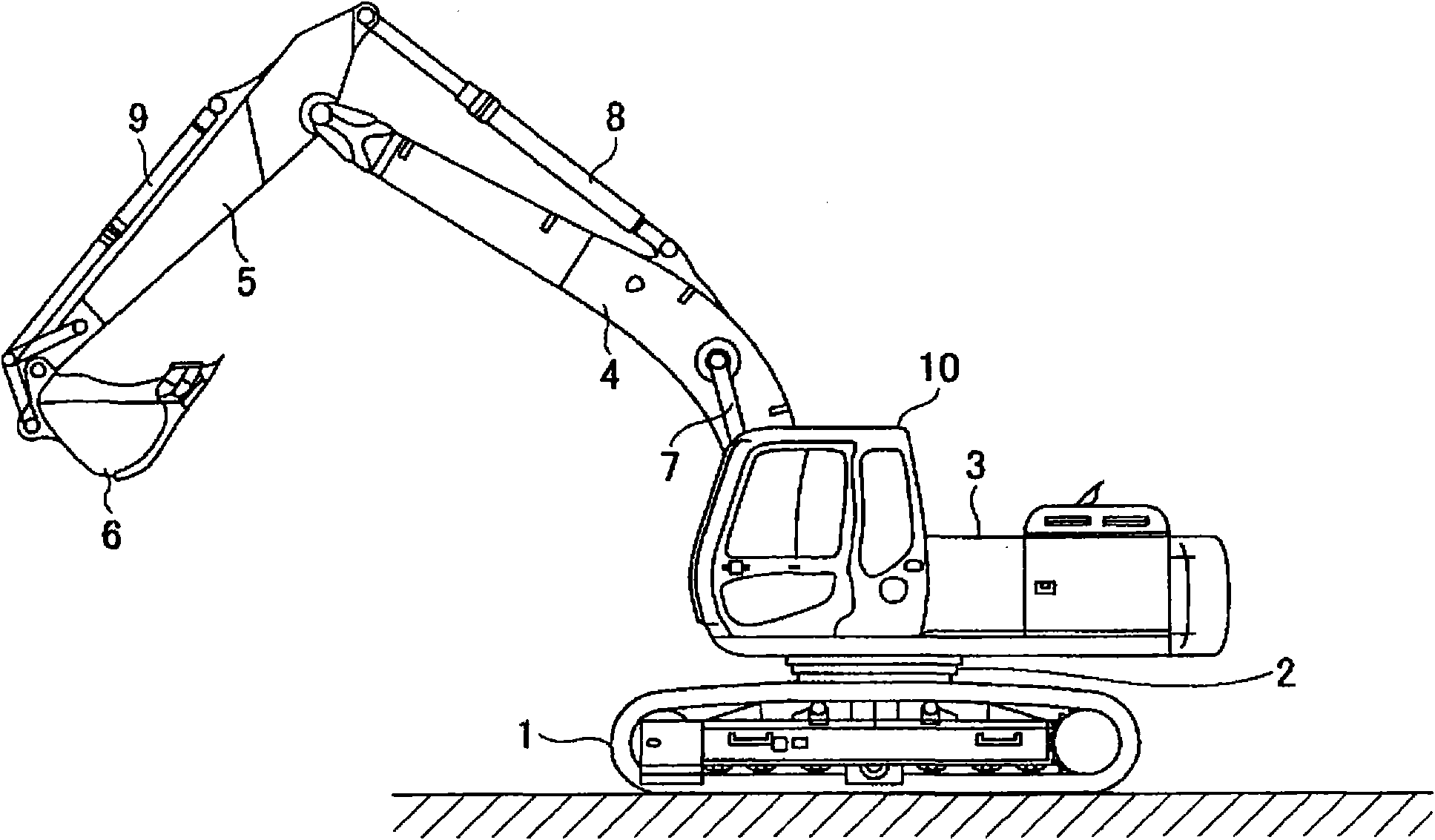
[0119] figure 1 It is a side view showing construction machines including the hybrid construction machine according to the first embodiment.
[0120] An upper revolving body 3 is mounted on a lower movable body 1 of this hybrid construction machine via a revolving mechanism 2 . In addition, the upper slewing body 3 is equipped with a cab 10 in addition to the boom 4, the rocker arm 5, and the bucket 6, and the boom cylinder 7, the rocker cylinder 8, and the bucket cylinder 9 for hydraulically driving them. and power source.
[0121] [the whole frame]
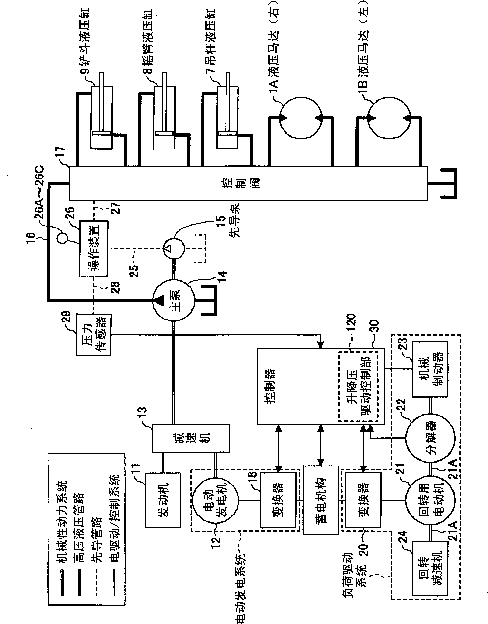
[0122] figure 2 It is a block diagram showing the configuration of the hybrid construction machine according to the first embodiment. in the figure 2 In the figure, the mechanical power system is represented by double lines, the high-pressure hydraulic lines are represented by thick solid lines, the pilot line is represented by dotted lines, and the electric drive / control system is represented by solid lines.
[0123] An...
Embodiment approach 2
[0184] Figure 4 It is a diagram showing the circuit configuration of the control device used in the buck-boost converter 100 of the hybrid type construction machine according to the second embodiment using control blocks. As shown in the figure, the buck-boost drive control unit 120 of the buck-boost converter 100 includes a voltage control unit 121 , a current control unit 122 , a control switching unit 123 , and a buck-boost switching unit 124 .
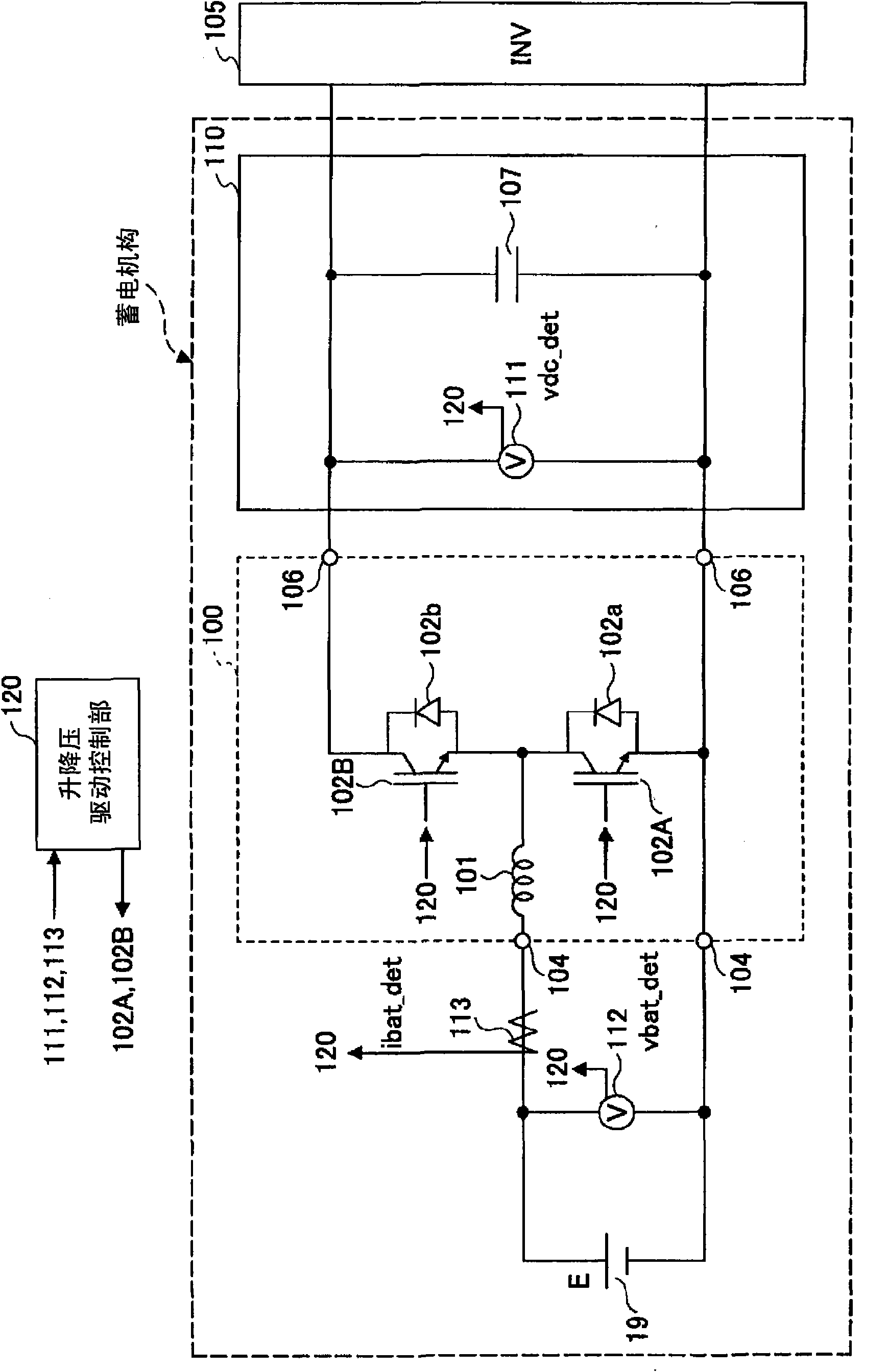
[0185] A power connection terminal 104 , an output terminal 106 , a PM (Power Module) 125 for boosting, and a PM 126 for stepping down are connected to the buck-boost drive control unit 120 . These can be achieved image 3 The connection is made in the way of the hardware structure shown. That is, the boost IGBT 102A and the step-down IGBT 102B included in the step-up PM 125 and the step-down PM 126 are PWM driven by the step-up and step-down drive control unit 120, and as a result, the battery voltage Vbat (= vbat_det) and the ...
Embodiment approach 3
[0238] The hybrid type construction machine of Embodiment 3 uses the same boost-boost converter 100 as that of Embodiment 1. As shown in FIG. Therefore, reference in Embodiment 3 image 3 . Embodiment 3 differs from Embodiment 1 in that instead of figure 2 The buck-boost drive control unit 120 according to Embodiment 1 shown uses the drive control unit 200 .
[0239] In the buck-boost converter 100, when the DC bus 110 is boosted, a PWM voltage is applied to the gate terminal of the boost IGBT 102A, and through the diode 102b connected in parallel with the step-down IGBT 102B, the DC bus 110 is switched on and off. On / Off The induced electromotive force generated in the reactor 101 is supplied to the DC bus 110 . Thus, DC bus 110 is boosted.
[0240] Then, when stepping down DC bus 110 , PWM voltage is applied to the gate terminal of step-down IGBT 102B, and regenerative power supplied from inverter 105 is supplied from DC bus 110 to battery 19 via step-down IGBT 102B. A...
PUM
 Abstract
Description
Claims
Application Information
 - R&D
- Intellectual Property
- Life Sciences
- Materials
- Tech Scout
- Unparalleled Data Quality
- Higher Quality Content
- 60% Fewer Hallucinations
Browse by: Latest US Patents, China's latest patents, Technical Efficacy Thesaurus, Application Domain, Technology Topic, Popular Technical Reports.
© 2025 PatSnap. All rights reserved.Legal|Privacy policy|Modern Slavery Act Transparency Statement|Sitemap|About US| Contact US: help@patsnap.com


