Novel Brillouin time domain analyzer

An optical time domain analyzer, a new type of technology, is used in instruments, scientific instruments, and measurement by measuring the change of optical properties of materials when they are stressed. It can solve the problems of high price and cost reduction, and achieve cost reduction, The effect of stable output pulse and high measurement accuracy

Active Publication Date: 2011-01-19
ZHEJIANG ZHONGXIN POWER MEASUREMENT & CONTROL TECH
View PDF9 Cites 12 Cited by
  • Summary
  • Abstract
  • Description
  • Claims
  • Application Information

AI Technical Summary

Problems solved by technology

However, the external optical modulation devices available on the market that meet the performance indicators are all imported and expensive, and in order to ensure the normal operation of the optical external modulation device, all optical devices between the detection light source and the optical modulation device must have polarization maintaining Performance, which has become a bottleneck restricting the cost reduction of Brillouin optical time domain analyzers

Method used


Image

  • Novel Brillouin time domain analyzer
  • Novel Brillouin time domain analyzer
  • Novel Brillouin time domain analyzer

Examples


Embodiment 1

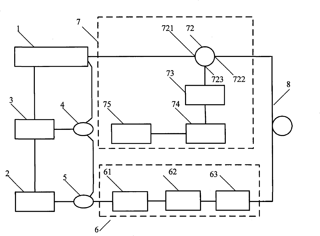
[0019] Embodiment one: if Figure 2-4 As shown, a new type of Brillouin optical time domain analyzer includes a pulse detection light generation module 1, a pump light source module 2, a frequency control module 3, a first optical coupler 4, a second optical coupler 5, a pump Optical output module 6, detection optical output and signal processing module 7 and detection optical fiber module 8, detection optical output and signal processing module 7 includes polarization controller 71, optical circulator 72, photoelectric conversion and signal amplification module 73, high-speed acquisition module 74 And the PC 75, the output end of the polarization controller 71 is connected with the input end 721 of the optical circulator 72, the first output end 722 of the optical circulator 72 is connected with the input end of the detection fiber module 8, and the second output end of the optical circulator 72 723 is connected with the photoelectric conversion and signal amplification modul...

Embodiment 2

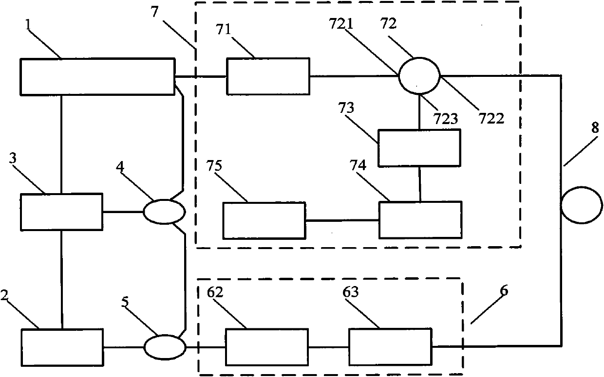
[0022] Embodiment two: if Figure 5 As shown, other structures are the same as the embodiment, the difference is that the polarization controller 71 in the detection light output and signal processing module 7 is moved to the pump light output module 6, at this time, the optical fiber of the pulse detection light generation module 1 The output end of the amplifier 14 is connected to the input port 721 of the optical circulator 72, and an output end of the second optical coupler 5 is connected to the input end of the polarization controller 61 in the pump light output module 6, so that the polarization state is The influence of the deep amplification effect is reduced to the minimum, the output end of the polarization controller 61 is connected with the input end of the optical attenuator 62, the optical attenuator 62 is an adjustable optical attenuator, after passing through the optical attenuator 62, the optical power is attenuated to a suitable value , so that the Brillouin ...


PUM

PropertyMeasurementUnit
lengthaaaaaaaaaa

Abstract

The invention discloses a novel Brillouin time domain analyzer, which comprises a pulse detection light generation module, a pump light source module, a first optical coupler, a second optical coupler, a frequency control module, a detection light output and signal processing module and a pump light output module, and is characterized in that: the pulse detection light generation module comprises a laser driving circuit capable of generating electric pulse signals, a narrow line width tunable semiconductor laser, a third optical coupler and an optical fiber amplifier; the laser driving circuit is connected with the frequency control module; the input end of the third optical coupler is connected with the narrow line width tunable semiconductor laser; two output ends of the third optical coupler are respectively connected with the input end of the optical fiber amplifier and another input end of the first optical coupler; and the output end of the optical fiber amplifier is connected with the detection light output and signal processing module. The novel Brillouin time domain analyzer has the advantages of low cost, high spacial resolution, high measurement accuracy and long measurement distance.

Description

technical field [0001] The invention relates to an optical time domain analyzer, in particular to a novel Brillouin optical time domain analyzer. Background technique [0002] Distributed temperature sensor (DTS) has important applications in the fields of safety monitoring of power cables, disaster prevention and alarm in key areas. At present, the commonly used DTS is to use the Raman scattering effect in the optical fiber to obtain the temperature changes along the optical fiber by measuring the back Raman scattered light intensity of the optical fiber. This measurement technology is now relatively mature, but due to the limitation of the detection light intensity, the current achievable spatial resolution is about 3 to 4 meters, the temperature measurement accuracy is greater than 1 degree, and the measurable optical fiber length generally does not exceed 10 kilometers . In addition, DTS based on Raman scattering technology needs to use multimode fiber as the measureme...

Claims


Application Information

Patent Timeline
Patent Type & Authority Applications(China)
IPC IPC(8): G01K11/32G01L1/24G01K11/322
Inventor 刘航杰任尚今李浩泉张婕
Owner ZHEJIANG ZHONGXIN POWER MEASUREMENT & CONTROL TECH
Why Eureka
Try Eureka