Outside loop control device and method for realizing plasma beam focusing in Hall thruster
A Hall thruster, plasma technology, applied in the direction of plasma, thrust reverser, and plasma utilization, can solve the problems of complex calculation, adjustment, poor controllability, etc., and achieve focusing, strong operability, and implementation process. simple effect
- Summary
- Abstract
- Description
- Claims
- Application Information
AI Technical Summary
Problems solved by technology
Method used
Image
Examples
specific Embodiment approach 1
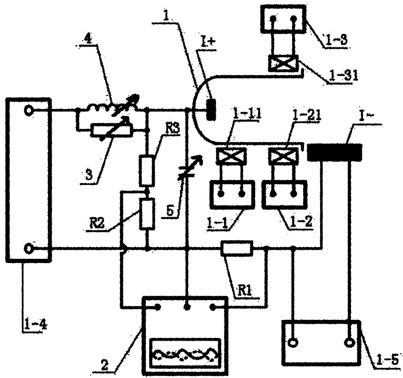
[0013] Specific implementation mode one: According to the instructions attached figure 1 This embodiment is described in detail. The outer loop control device for realizing the plasma beam focusing of the Hall thruster described in this embodiment, the control device includes the external power supply loop system of the Hall thruster 1, an oscilloscope 2, Variable resistor 3, adjustable inductance 4 and adjustable capacitor 5, the external power supply loop system includes a first power supply 1-1, a first coil 1-11, a second power supply 1-2, a second coil 1-21, The third power supply 1-3, the third coil 1-31, the fourth power supply 1-4, the fifth power supply 1-5, the first resistor R1, the second resistor R2 and the third resistor R3,
[0014] The two power output terminals of the first power supply 1-1 are respectively connected to the two ends of the first coil 1-11, and the two power output terminals of the second power supply 1-2 are respectively connected to the two e...
specific Embodiment approach 2
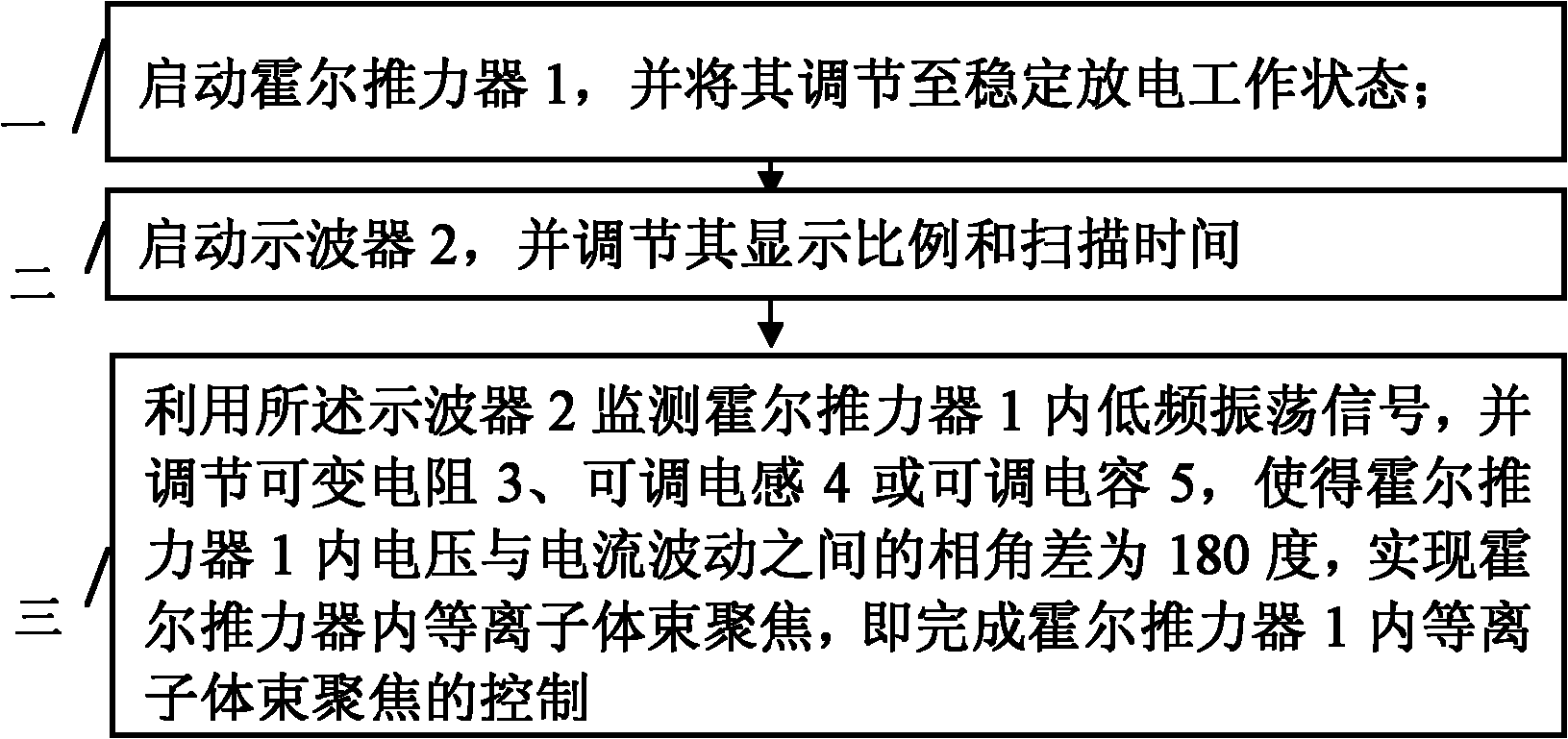
[0018] Specific implementation mode two: according to the instructions attached figure 2 Describe this embodiment in detail. This embodiment is an outer loop control method for realizing the plasma beam focusing of a Hall thruster based on the outer loop control device described in Embodiment 1. The control method includes the following steps:
[0019] Step 1: Start the Hall thruster 1 and adjust it to a stable discharge working state;
[0020] Step 2: Start the oscilloscope 2, and adjust its display scale and sweep time;
[0021] Step 3: Use the oscilloscope 2 to monitor the low-frequency oscillation signal in the Hall thruster 1, and adjust the variable resistor 3, adjustable inductance 4 or adjustable capacitor 5, so that the voltage and current fluctuations in the Hall thruster 1 The phase angle difference is 180 degrees to realize the focus of the plasma beam in the Hall thruster, that is, to complete the control of the focus of the plasma beam in the Hall thruster 1 . ...
specific Embodiment approach 3
[0023] Specific embodiment three: This embodiment is a further description of specific embodiment two. In specific embodiment two, the stable discharge working state of the Hall thruster 1 described in step one is: the discharge voltage is 400V, and the anode I+gas supply The flow rate is 3mg / s, and the magnetic field configuration is fixed.
PUM
 Abstract
Description
Claims
Application Information
 - R&D
- Intellectual Property
- Life Sciences
- Materials
- Tech Scout
- Unparalleled Data Quality
- Higher Quality Content
- 60% Fewer Hallucinations
Browse by: Latest US Patents, China's latest patents, Technical Efficacy Thesaurus, Application Domain, Technology Topic, Popular Technical Reports.
© 2025 PatSnap. All rights reserved.Legal|Privacy policy|Modern Slavery Act Transparency Statement|Sitemap|About US| Contact US: help@patsnap.com


