
Method for detecting surface enhanced raman spectrum based on interference and diffraction stimulation

A surface-enhanced Raman and spectral detection technology, which is applied in Raman scattering, scattering characteristic measurement, material excitation analysis, etc., to achieve the effect of increasing energy density, effective excitation, and increasing emission intensity

Inactive Publication Date: 2011-03-02
JILIN UNIV
View PDF7 Cites 7 Cited by
  • Summary
  • Abstract
  • Description
  • Claims
  • Application Information

AI Technical Summary

Problems solved by technology

There is no patent on grating-coupled SPR excitation SERS in domestic published patents

Method used


Image

  • Method for detecting surface enhanced raman spectrum based on interference and diffraction stimulation
  • Method for detecting surface enhanced raman spectrum based on interference and diffraction stimulation
  • Method for detecting surface enhanced raman spectrum based on interference and diffraction stimulation

Examples


Embodiment 1

[0034] Embodiment 1 illustrates various substrates of the present invention in conjunction with the accompanying drawings to implement the detection of surface-enhanced Raman spectroscopy

specific Embodiment approach

[0035] The specific implementation method comprises the following steps:

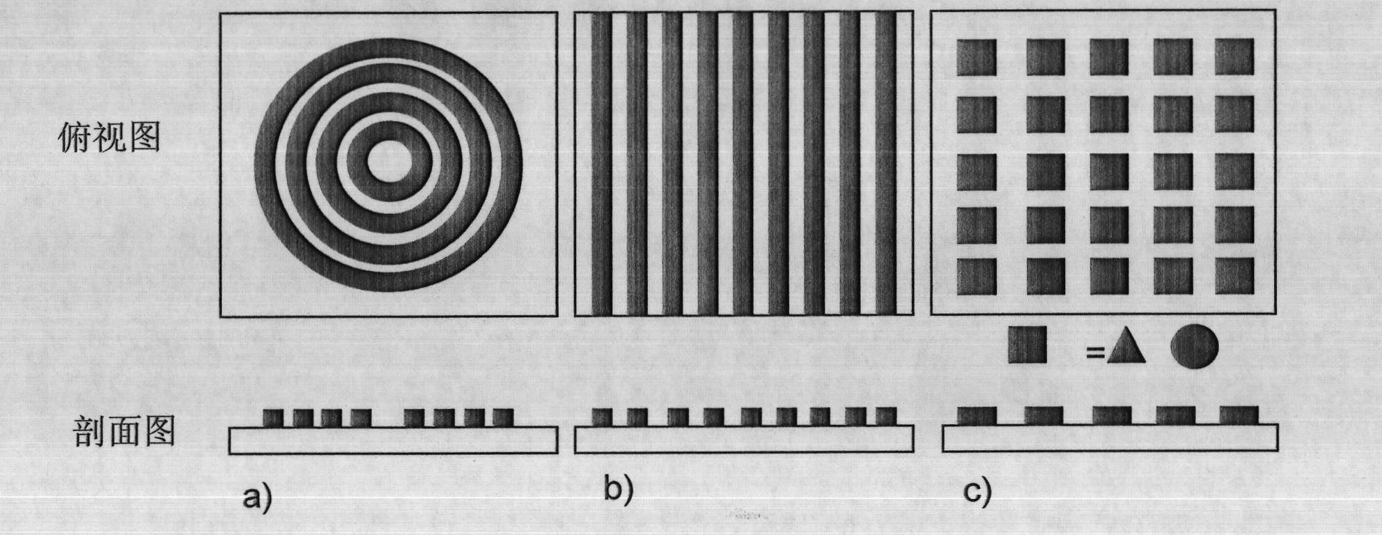
[0036]1. Prepare one-dimensional, two-dimensional or three-dimensional periodic micro-nano structures with a size range of micron or submicron. The method for preparing the periodic microstructure metal layer is microfabrication technology, including template method (for example, using different scale porous alumina templates, porous silicon templates, and colloidal crystals as templates), imprinting technology, electron beam exposure technology, Metal lift-off technology, dry etching technology, etc. build as figure 1 Shown is a periodic ring structure (a), a micro-nano strip grating structure (b) or a lattice structure (c). Each point in the lattice structure can be square, triangular or circular.

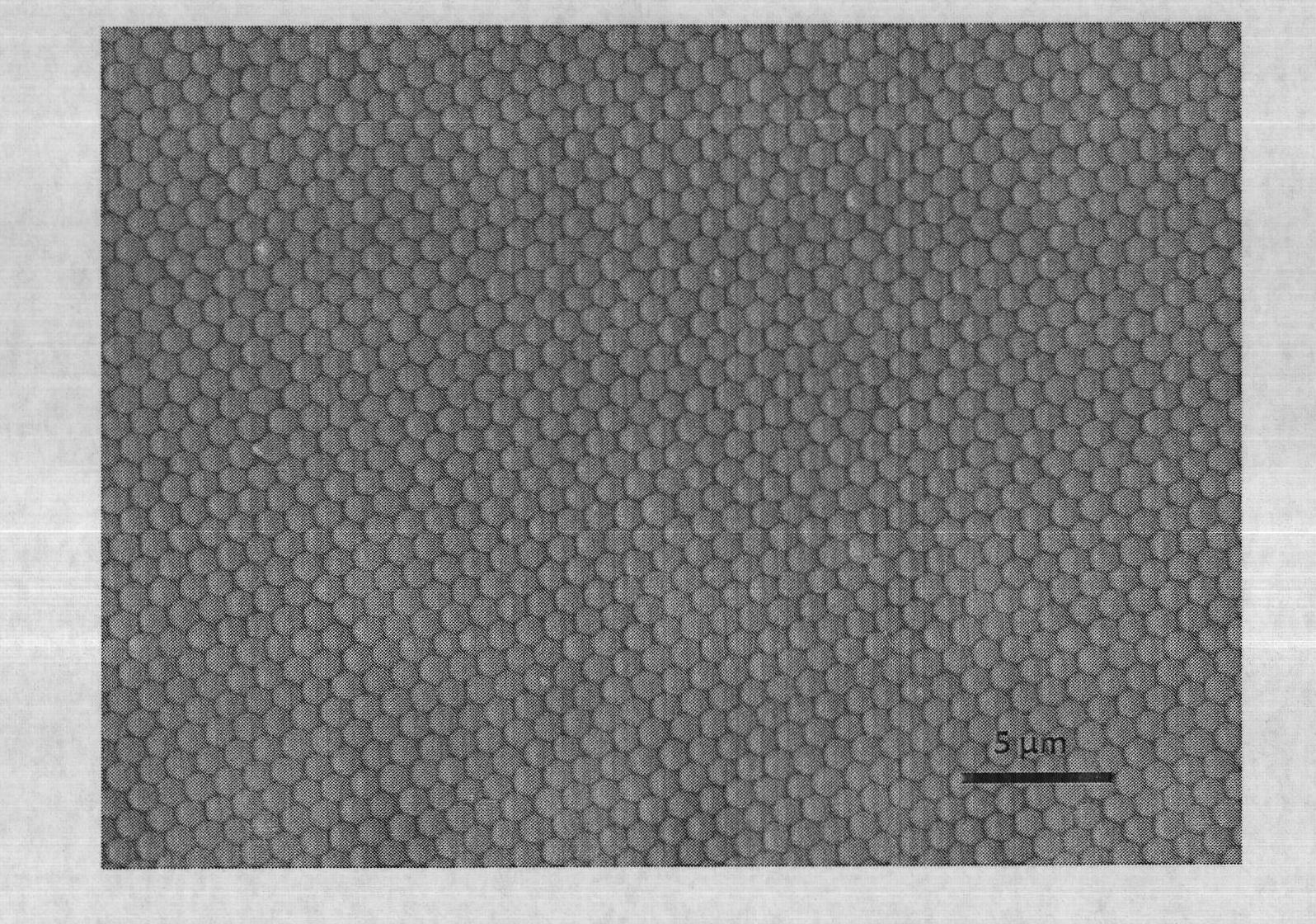
[0037] 2. Modify metal (1) films or other nanostructures on periodic microstructures, such as image 3 The silver film is evaporated on the ordered two-dimensional array of polystyrene microspheres sho...

Embodiment 2

[0040] Example 2 Surface Enhanced Raman Spectroscopy Detection of Rhodamine 6G Molecules Using a Metal Strip Structure Substrate

[0041] 1. A periodic strip structure with a period of 1.5 microns and a depth of 150 nanometers is prepared on a metal or non-metal substrate by photolithography or nanoimprinting technology.

[0042] 2. Evaporate a 150nm thick silver film on the periodic strip structure to make a SERS substrate. After coating, it still has a good periodic grating structure, and its optical picture is as follows Figure 5 shown. Rhodamine 6G molecule solution (10 -4 M) Drop it on the periodic substrate and let it dry for later use.

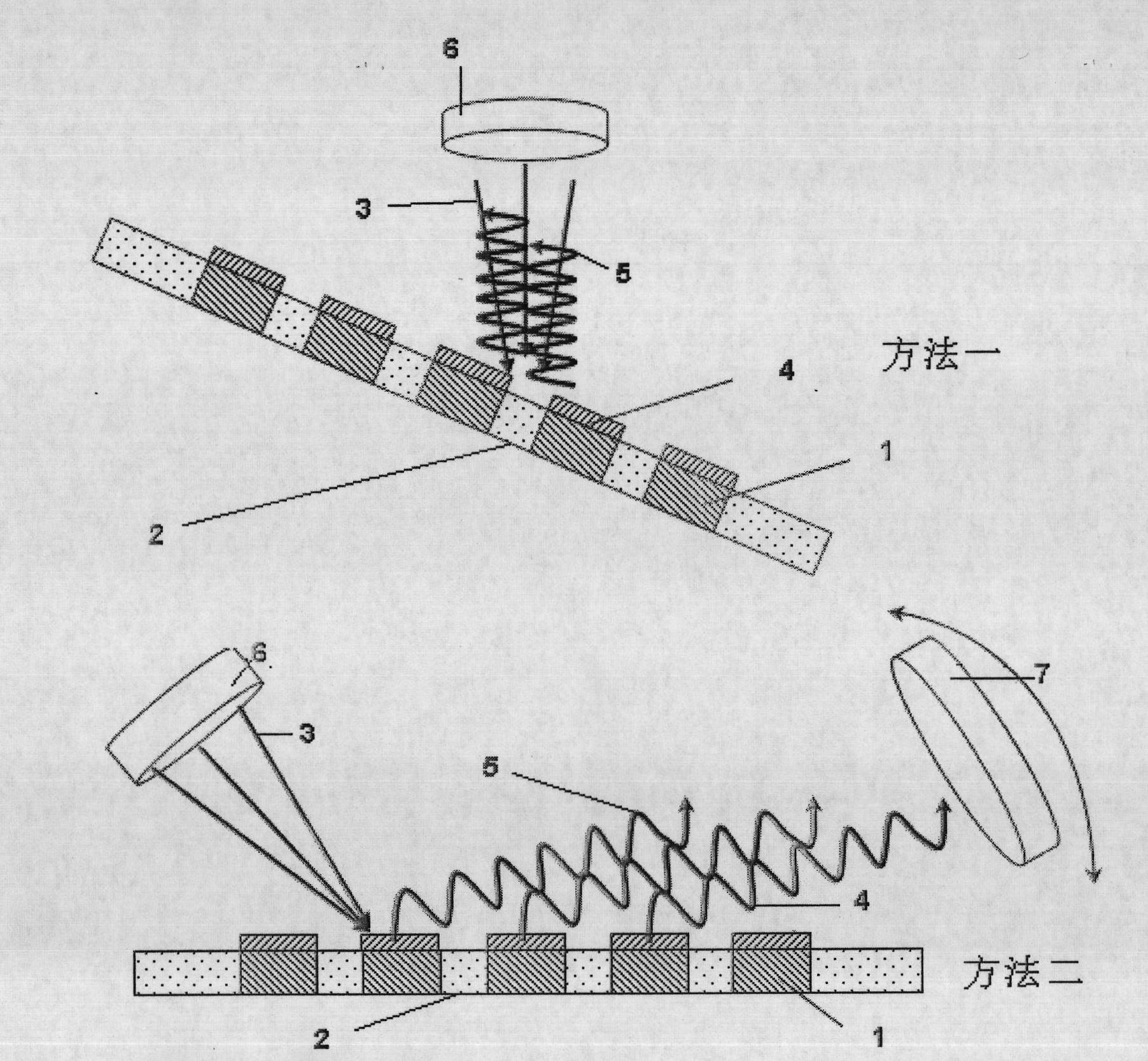
[0043] 3. Measure the reflectance of the P-polarized 785nm laser at different angles on the substrate adsorbed on the sample, such as Image 6 . The angle of 34 degrees corresponding to the lowest point of the reflectivity, that is, the minimum point of the curve, is the SPR incident resonance angle.

[0044] 4. Use figure 2 Th...


PUM


Abstract

The method for detecting a surface enhanced raman spectrum based on interference and diffraction stimulation of the invention belongs to the technical field of spectral analysis and detection. The method comprises the steps of: using a surface enhanced raman spectrum substrate having a periodic microstructure with a periodic size range from 0.05 to 50 microns, emitting the P polarized lasers with wavelength as same as the wavelength for stimulating the raman on the substrate which is absorbed with the sample from different angles, measuring the laser reflectivity of the base, using an incidence angle corresponding to the low reflectivity as the surface plasma incidence resonance angle with the stimulated raman wavelength, emitting the P polarized lasers under the incidence resonance angle on the base absorbed with the sample and receiving a raman signal along the reflection resonance angle. The method of the invention can efficiently stimulate the surface plasma and centrally emit the SERS signals under the resonance angle, therefore increasing the energy density of the signal and promoting the collecting effect of the light signals.

Description

technical field [0001] The present invention is related to the analysis and detection technology of spectra, in particular to a technology capable of exciting and detecting surface-enhanced Raman spectroscopy by means of interference and diffraction, thereby improving the spectral detection quality of surface-enhanced Raman scattering signals and improving the sensitivity of analysis and detection. Background technique [0002] The surface-enhanced Raman scattering effect (Surface-enhanced Raman Scattering, SERS) means that the sample Raman signal can be obtained on metal nanostructures and materials up to 10 4 ~10 10 enhancement. The development of Surface-enhanced Raman spectroscopy (SERS) technology has gone through several stages. People have continuously discussed and debated the mechanism of SERS, and put forward a variety of theoretical models, but they can be generally divided into physical enhancement models and chemical enhancement models. Currently, one of the ...

Claims


Application Information

Patent Timeline
Patent Type & Authority Applications(China)
IPC IPC(8): G01N21/65G01N21/49
Inventor 徐抒平徐蔚青李海波
Owner JILIN UNIV
Learn More