
Negative plate of inert composite electrode adopting EFT and preparation method thereof and electrolytic equipment containing negative plate

A technology for electrolysis equipment and electrode plates, applied in electrodes, electrolysis process, electrolysis components, etc., can solve the problems of easy fouling, high consumption of electrode plate materials, and short service life.

Inactive Publication Date: 2011-03-16
蒋亚熙 +1
View PDF4 Cites 3 Cited by
  • Summary
  • Abstract
  • Description
  • Claims
  • Application Information

AI Technical Summary

Problems solved by technology

[0011] At the same time, the soluble electrodes widely used at home and abroad are mostly iron plates and aluminum plates as flocculants for sewage treatment, but the material consumption of the electrode plates is too high, easy to accumulate fouling, easy to age, and the service life is short (about 30 days), which increases the Wastewater Treatment Costs

Method used


Image

  • Negative plate of inert composite electrode adopting EFT and preparation method thereof and electrolytic equipment containing negative plate
  • Negative plate of inert composite electrode adopting EFT and preparation method thereof and electrolytic equipment containing negative plate
  • Negative plate of inert composite electrode adopting EFT and preparation method thereof and electrolytic equipment containing negative plate

Examples


Embodiment 1

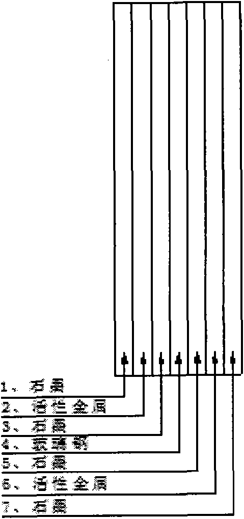
[0117] Embodiment 1. cathode plate, a 7-layer structure composed of graphite layer, iron layer after sprinting, graphite layer, glass fiber reinforced plastic layer, graphite layer, iron layer and graphite layer after sprinting

[0118] Step 1: Preparation of Graphite Layer

[0119] Select high-quality expanded graphite worms with a content of more than 99.8% and press them into 4 composite flat plates with a thickness of 0.8mm.

[0120] Step 2: Preparation of FRP layer

[0121] Use high-quality epoxy resin and glass fiber to press into a composite plate with a thickness of 0.6mm.

[0122] Step 3: Preparation of active metal layer

[0123] Two pieces of active metallic iron materials with a thickness of 1mm are selected for sprint treatment.

[0124] Step 4: Preparation of transition plate

[0125] The 0.8mm graphite layer, the 1mm thick punctured active metal iron layer and the 0.8mm graphite layer were sequentially bonded and flattened with glue to obtain two composite m...

Embodiment 2

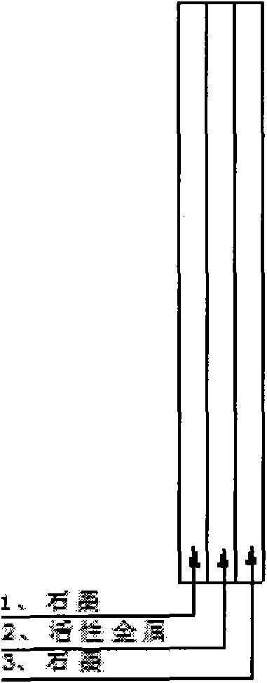
[0127] Embodiment 2. cathode plate, a 3-layer structure consisting of graphite layer, aluminum layer and graphite layer in turn

[0128] Step 1: Preparation of Graphite Layer

[0129] Select high-quality expanded graphite worms with a content of more than 99.8% and press them into 2 composite flat plates with a thickness of 0.6mm.

[0130] Step 2: Preparation of active metal layer

[0131] The active metal aluminum material with a thickness of 1mm is selected.

[0132] Step 3: Preparation of transition plate

[0133] After the 0.6mm graphite layer, the 1mm thick active metal aluminum layer and the 0.6mm graphite layer are glued and flattened sequentially, the cathode plate of the present invention is obtained.

Embodiment 3

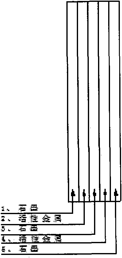
[0134] Embodiment 3. cathode plate, 5 layer structure that is formed successively by graphite layer, aluminum layer, graphite layer, aluminum layer, graphite layer

[0135] Step 1: Preparation of Graphite Layer

[0136] Select high-quality expanded graphite worms with a content of more than 99.8% and press them into 3 composite flat plates with a thickness of 0.8mm.

[0137] Step 2: Preparation of active metal layer

[0138] The active metal aluminum material with a thickness of 1mm is selected.

[0139] Step 3: Preparation of transition plate

[0140] After the graphite layer, the active metal aluminum layer, the graphite layer, the active metal aluminum layer and the graphite layer are sequentially glued and flattened, the cathode plate of the present invention is obtained.


PUM

PropertyMeasurementUnit
Thicknessaaaaaaaaaa
Thicknessaaaaaaaaaa
Thicknessaaaaaaaaaa

Abstract

The invention relates to an electrode plate of an inert composite electrode adopting environment friendly technology (EFT), in particular to a negative plate of the inert composite electrode, and a preparation method and application of the electrode plate. After using the electrode plate, the treated sewage can be discharged up to the standard and the service life of the electrode plate is greatly prolonged.

Description

technical field [0001] The invention relates to an electrode plate of an inert composite electrode of environment friendly technology (EFT, Environment Friendly Technology), especially a cathode plate of an inert composite electrode, a preparation method of the electrode plate and an application thereof. Background technique [0002] Electrochemical water treatment technology is called "environmentally friendly" technology (EFT, Environment Friendly Technology. The main points of EFT electrochemical technology are: electrocoagulation / electrical floatation / co-precipitation technology, which is the application of electrochemical redox reaction principle, control Electrochemical method of pollution. Direct current of a certain voltage is passed into the electrolytic cell, and the wastewater passes through the electrolytic cell, so that the anion of the electrolyte in the wastewater moves to the anode, loses electrons at the anode and is oxidized, and the cation moves to the cath...

Claims


Application Information

Patent Timeline
IPC IPC(8): C25B11/00C02F1/461
CPCC02F1/46109C02F2001/46142
Inventor 蒋亚熙张定军
Owner 蒋亚熙
Learn More