Polysilicon reducing furnace with multiple gas outlets on chassis

A technology of gas outlet and reduction furnace, applied in silicon and other directions, can solve the problems of uneven upper and lower thickness of polycrystalline silicon rods, uneven distribution of gas flow field, affecting the deposition speed of polycrystalline silicon, etc., so as to improve the one-time conversion rate, flow and mass transfer. The effect of reducing dead zone and uniform thickness up and down

Inactive Publication Date: 2011-04-06
TIANJIN UNIV
View PDF4 Cites 18 Cited by
  • Summary
  • Abstract
  • Description
  • Claims
  • Application Information

AI Technical Summary

Problems solved by technology

The main problems in the existing technology are: since the chassis is only provided with one gas outlet, the flow of the reentrant downward gas and the tail gas generated by the reaction is uneven, resulting in uneven distributi

Method used


Image

  • Polysilicon reducing furnace with multiple gas outlets on chassis
  • Polysilicon reducing furnace with multiple gas outlets on chassis
  • Polysilicon reducing furnace with multiple gas outlets on chassis

Examples


Embodiment 1

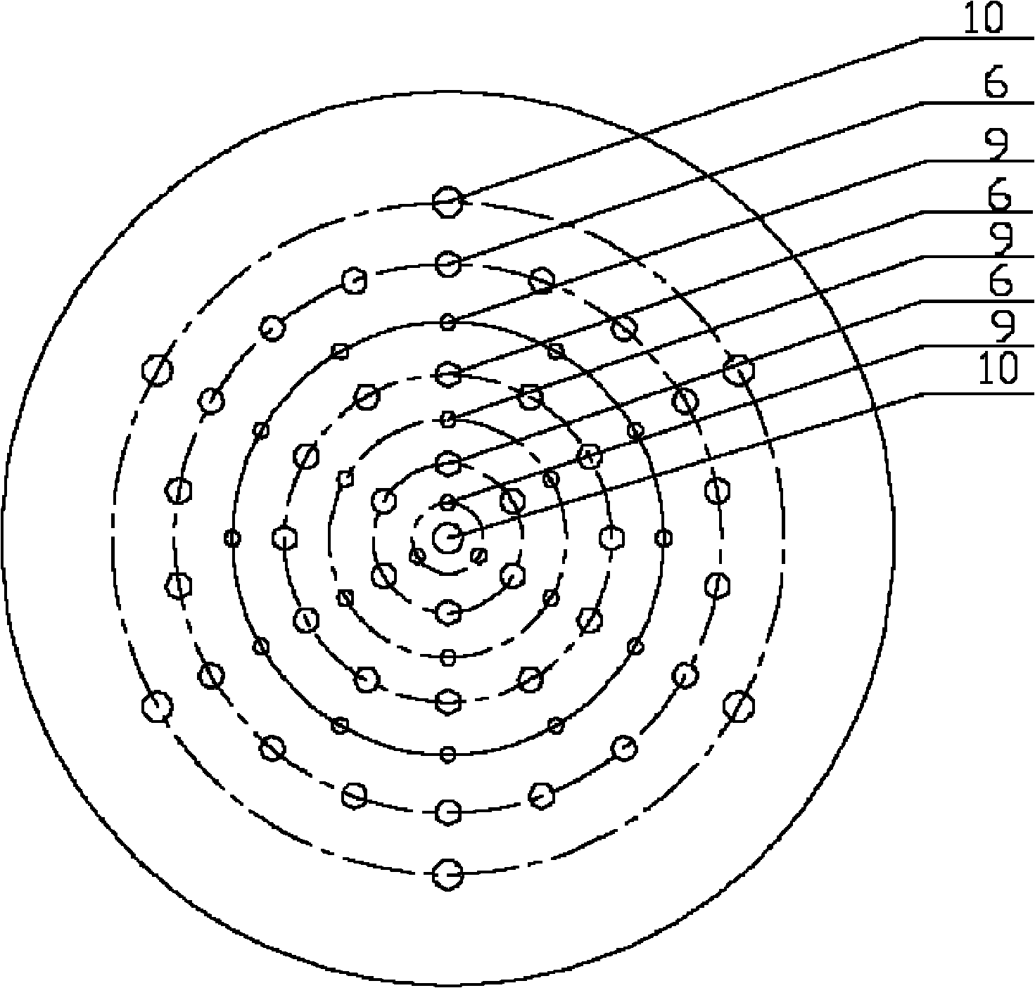
[0022] Embodiment 1: as Figure 2a As shown, there are 18 pairs of electrodes in the furnace, which are evenly arranged on the chassis in 3 circles, 3 pairs in the inner circle, 6 pairs in the middle circle, and 9 pairs in the outer circle; several air inlet nozzles are evenly distributed on the chassis in 3 circles ; The air outlets are arranged on the chassis in two circles, one air outlet is set in the center of the chassis, and 6 air outlets are set in the outermost circle of the chassis. The overall layout on the chassis is that the 1st (chassis center) and 8th circles are air outlets 10, the 2nd, 4th, and 6th circles are air inlets 9, and the 3rd, 5th, and 7th circles are electrodes 6.

Embodiment 2

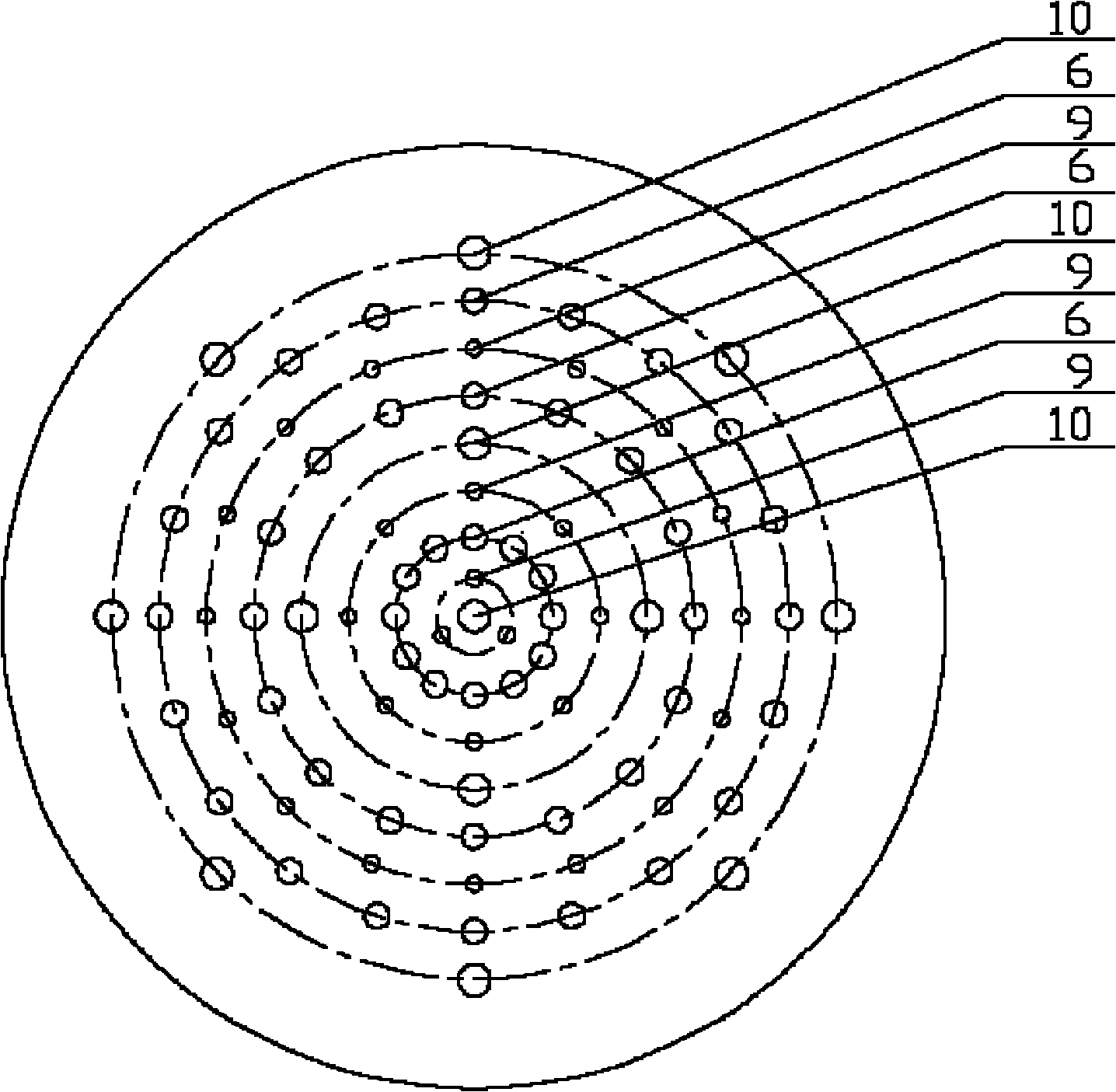
[0023] Embodiment 2: as Figure 2b As shown, there are 24 pairs of electrodes in the furnace, arranged on the chassis in 3 circles, 6 pairs in the inner circle, 8 pairs in the middle circle, and 10 pairs in the outer circle; several air inlet nozzles are evenly distributed on the chassis in 3 circles; The air outlets are arranged on the chassis in 3 circles, one air outlet is set in the center of the chassis, 4 air outlets are evenly arranged in a circle between the second circle of air inlet nozzles and the second circle of electrodes, and 8 air outlets are arranged in the The outermost ring position of the chassis. The overall arrangement on the chassis is that the 1st (chassis center), 5th, and 9th circles are air outlets 10, the 2nd, 4th, and 7th circles are air inlets 9, and the 3rd, 6th, and 8th circles are electrodes 6.

Embodiment 3

[0024] Embodiment 3: as Figure 2c As shown, there are 36 pairs of electrodes in the furnace, arranged on the chassis in 3 circles, 6 pairs in the inner circle, 12 pairs in the middle circle, and 18 pairs in the outer circle; several air inlet nozzles are evenly distributed on the chassis in 3 circles; The air outlets are arranged on the chassis in 3 circles, one air outlet is set in the center of the chassis, 6 air outlets are evenly arranged in a circle between the second circle of electrodes and the third circle of intake nozzles, and 10 air outlets are arranged in the The outermost ring position of the chassis. The overall arrangement on the chassis is that the 1st (chassis center), 6th, and 9th circles are air outlets 10, the 2nd, 4th, and 7th circles are air inlets 9, and the 3rd, 5th, and 8th circles are electrodes 6.

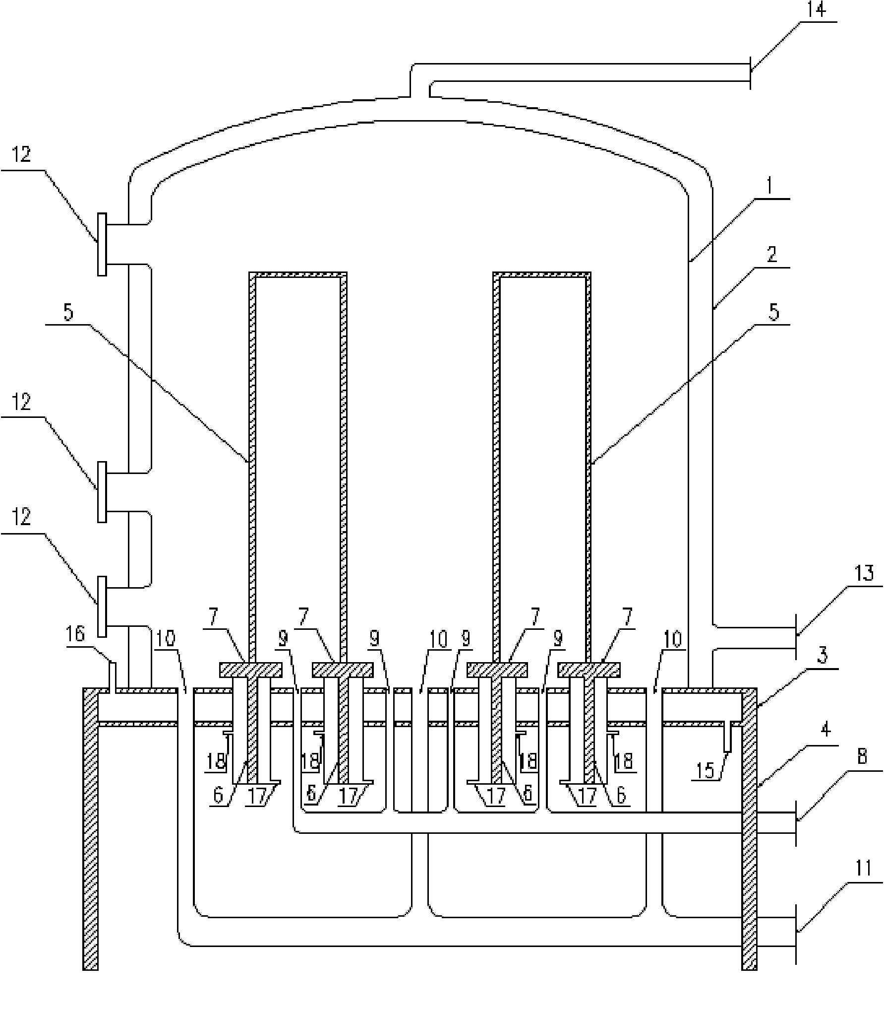
[0025] The mixed gas of hydrogen and trichlorosilane is sprayed into the reduction furnace 1 through the inlet pipe 8 and several nozzles 9 arranged on...


PUM


Abstract

The invention discloses a polysilicon reducing furnace with multiple gas outlets on the chassis. The polysilicon reducing furnace comprises a furnace body, a jacket, a chassis, a support, a plurality of pairs of electrodes, a silicon core, a mixed gas inlet pipe and inlet nozzle, a plurality of gas outlets and gas outlet pipes, a cooling system, an observation sight glass and the like. The polysilicon reducing furnace is characterized in that a plurality of gas outlets are arranged on the chassis of the reducing furnace, the gas outlets are uniformly distributed on the chassis in circles. As a plurality of gas outlets are arranged on the chassis in the furnace, the inner space of the furnace can be full of the gas moving back to the bottom and the tail gas obtained by the reaction, the gases can flow downward uniformly to the gas outlets on the chassis to be discharged and the gases can be distributed uniformly in the entire furnace. The advantage of uniform gas distribution in the furnace can be more remarkable when the chassis of the high-capacity reducing furnace is provided with a plurality of gas outlets. As the gas in the furnace is distributed uniformly, the deposition rate of silicon on the surface of the silicon rod can be accelerated, the thickness of the obtained rod-shaped polysilicon product is uniform from top to bottom and both quality and yield of the product can be increased.

Description

technical field [0001] The invention relates to a polysilicon production equipment, in particular to a polysilicon reduction furnace. Background technique [0002] At present, polysilicon production enterprises mainly adopt the improved Siemens method. The production process of this method is to use chlorine and hydrogen to synthesize hydrogen chloride (or purchased hydrogen chloride), hydrogen chloride and metallurgical silicon powder to synthesize trichlorosilane at a certain temperature, and the trichlorosilane after separation and rectification purification enters the reduction furnace and is reduced by hydrogen , to produce high-purity polysilicon by chemical vapor deposition reaction. The process includes five main links: synthesis of trichlorosilane, rectification and purification of trichlorosilane, hydrogen reduction of trichlorosilane, recovery of tail gas and hydrogenation separation of silicon tetrachloride. [0003] Among them, the hydrogen reduction of trichl...

Claims


Application Information

Patent Timeline
IPC IPC(8): C01B33/03
Inventor 黄国强段长春李雪刘春江
Owner TIANJIN UNIV
Why Eureka
Try Eureka