Multilayer fluidized bed gasification furnace for preparing methane-rich gas by coal gasification

A fluidized bed gasifier and multi-layer fluidized bed technology, applied in the field of gasifiers, can solve the problems of low reaction volume utilization rate, prolong the residence time of pulverized coal, affect solid phase processing, etc., and achieve the realization of logistics coupling, The effect of prolonging the average residence time and increasing the gas production capacity

Active Publication Date: 2011-04-20
ENN SCI & TECH DEV
View PDF6 Cites 9 Cited by
  • Summary
  • Abstract
  • Description
  • Claims
  • Application Information

AI Technical Summary

Problems solved by technology

The device prolongs the residence time of pulverized coal, which is beneficial to solid-phase processing and has a high utilization rate of heat energy, but the reaction volume utilization rate in the gasifier is low, which affects solid-phase processing; the carbon content in the residue is high during vertical furnace operation, which is difficult Effective utilization; compared with gas-solid contact heat transfer, the heat transfer rate is slow, and the solid phase in the bed is heated unevenly; at the same time, the equipment is complicated, especially the horizontal furnace

Method used


Image

  • Multilayer fluidized bed gasification furnace for preparing methane-rich gas by coal gasification
  • Multilayer fluidized bed gasification furnace for preparing methane-rich gas by coal gasification
  • Multilayer fluidized bed gasification furnace for preparing methane-rich gas by coal gasification

Examples


Embodiment 1

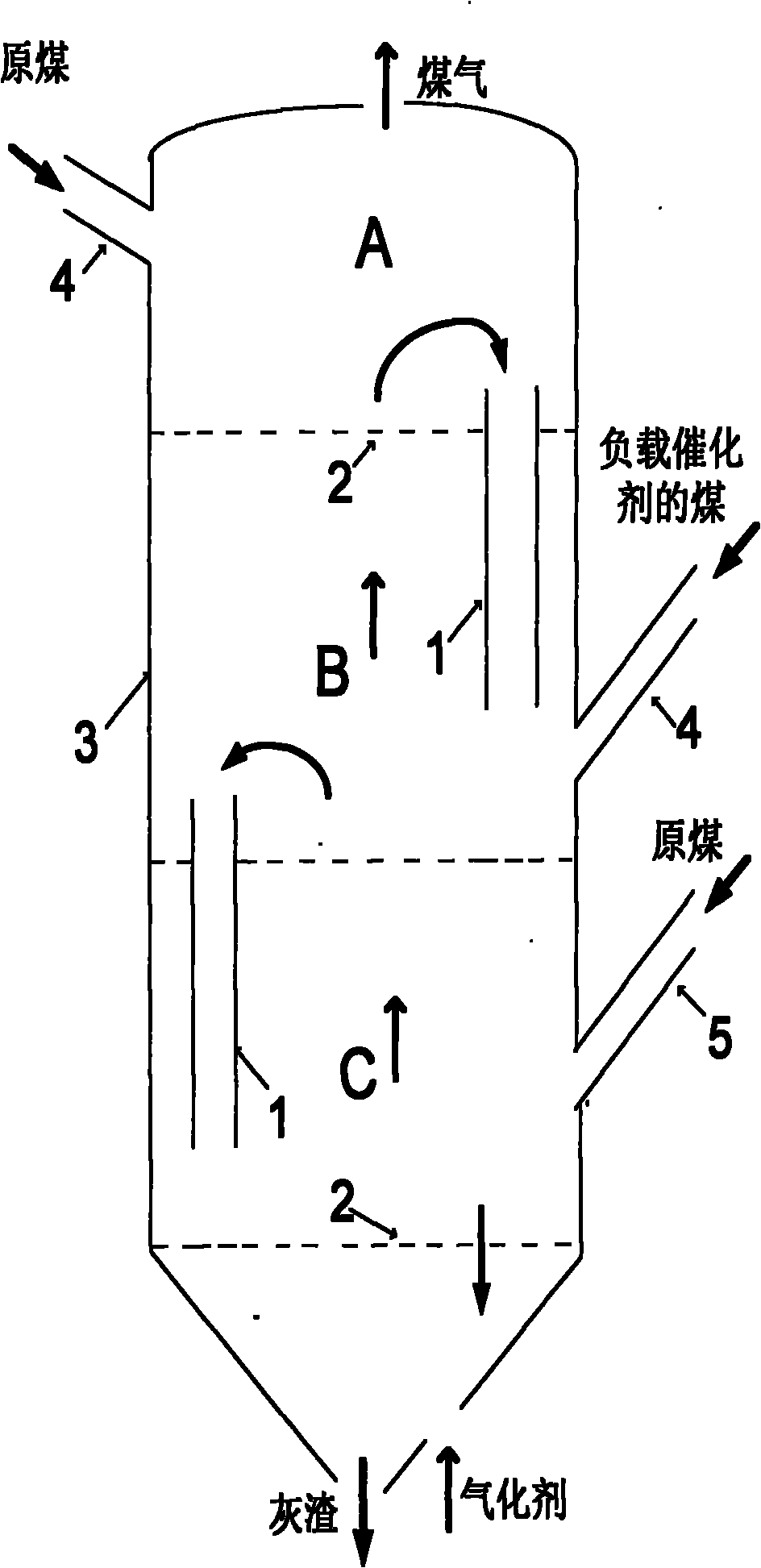
[0108] see figure 2 , in the structure figure 1 If the heat generated by the gasification of residues alone is difficult to meet the temperature requirements for catalytic gasification, a feed inlet 5 can be set on the furnace body 3 of the lowermost layer C of the multi-layer fluidized bed, through which the feed Add a small amount of raw coal to the residue gasification zone.

Embodiment 2

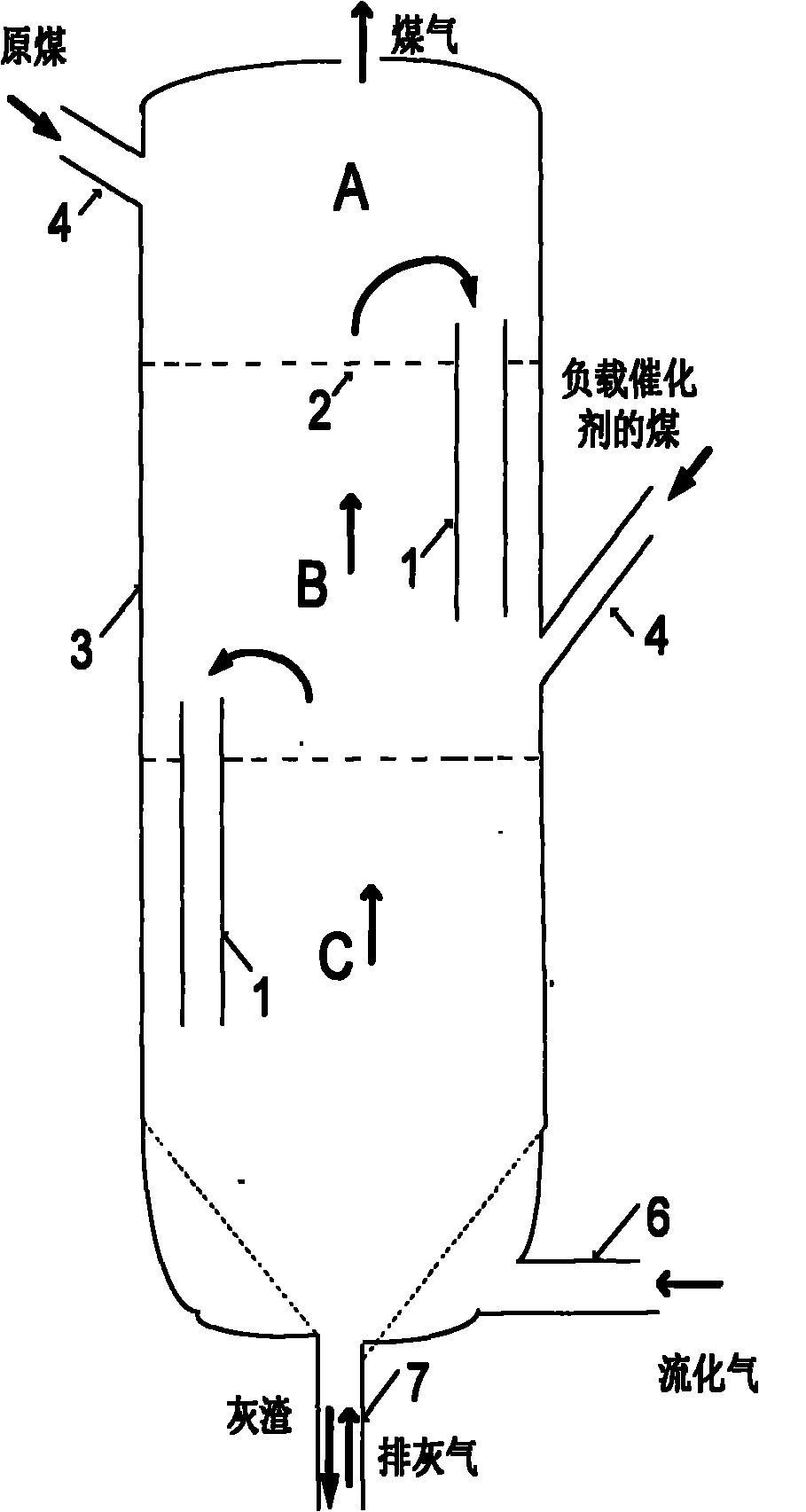
[0110] see image 3 , in the structure figure 1 In order to meet the needs of ash discharge or process operation conditions, the distribution plate of the lowest layer C of the multi-layer fluidized bed can be replaced, and the funnel-shaped distribution plate can be used to control the ash discharge gas velocity and flow through the air inlets 6 and 7 respectively. gasification speed.

Embodiment 3

[0112] see Figure 4 , in the structure figure 1 In order to avoid the reverse series of gas, to achieve continuous and stable overflow between the beds, and to facilitate the control of the overflow flow of the material, other forms of overflow pipes can be used, such as plug-type overflow pipes with mechanical transmission devices . Adjust the position of the plug 8 through the mechanical transmission device, change the direction of the gas and the size of the cross-section of the discharge port, and realize a smooth overflow.

[0113] Regarding the relative position of the overflow device and the gas distributor:

[0114] 1. The overflow pipe can be installed at any horizontal section of the gas distributor 2. It can be installed vertically or obliquely, and the angle with the horizontal plane is greater than or equal to 30°; in order to prevent solid particles from flowing between the two overflow pipes Short circuit, the outlet of the upper overflow pipe should keep...


PUM


Abstract

The invention discloses a multilayer fluidized bed gasification furnace for preparing a methane-rich gas by coal gasification. The multilayer fluidized bed gasification furnace comprises a gasification furnace shell, at least two layers of gas distributors, a raw material inlet, a clinker outlet, a gasification agent inlet, a coal gas outlet, a first overflow device and a second overflow device, wherein the gas distributors are perpendicular to a longitudinal axis and arranged at different heights along the longitudinal axis in a perforated plate form to partition the internal space into an upper space, a middle space and a lower space; the clinker outlet and the gasification agent inlet are positioned at the bottom of the shell; the coal gas outlet is positioned on the top of the shell; and the first overflow device and the second overflow device are penetrated into the first gas distributor and the second gas distributor respectively and each of the first overflow device and the second overflow device is tubular, and has two open ends, so that a raw material flows from the upper space to the middle space through the first overflow device along a curved line and then flows to the lower space from the middle layer through the second overflow device.

Description

technical field [0001] In general, the present invention relates to a gasification furnace, and in particular, the present invention relates to a multilayer fluidized bed gasification furnace for preparing methane-rich gas from coal gasification. Background technique [0002] The invention relates to a multilayer fluidized bed gasification furnace device for producing gas rich in methane by gasifying pulverized coal in a multilayer fluidized bed. [0003] my country is a country rich in coal, poor in oil and little in gas. With the rapid development of society and economy, the demand for natural gas in my country has risen sharply, and its proportion in the energy structure has increased rapidly. However, domestic natural gas is still in the early stages of exploration and development, imports are also in the initial stage, and the supply capacity is seriously lagging behind, resulting in increasingly prominent contradictions between natural gas supply and demand. Utilizing...

Claims


Application Information

Patent Timeline
Patent Type & Authority Applications(China)
IPC IPC(8): C10J3/56
Inventor 毕继诚李克忠程相龙张荣孙东凯李金来甘中学
Owner ENN SCI & TECH DEV
Why Eureka
Try Eureka