Solar charging control circuit

A charging control and solar cell technology, applied in the field of electric power, can solve the problems of different charging current, easily damaged batteries, and different recovery of battery capacity, achieve high-precision temperature compensation function, improve energy conversion efficiency, and accurate charging control.

Active Publication Date: 2011-04-27
EAST GRP CO LTD
View PDF5 Cites 35 Cited by
  • Summary
  • Abstract
  • Description
  • Claims
  • Application Information

AI Technical Summary

Problems solved by technology

Repeatedly, the charging controller is very prone to oscillation, which not only makes the controller not work normally, but also easily damages the battery.
At the same time, when charging the battery, a large current will cause energy loss, and a large amount of gas will be generated in the later stage of charging, which will shorten the life of the battery. However, charging with a small current takes a long time, and it cannot be charged quickly, and the charging current is different. The recovery of battery capacity is also different
[0005] 2. After the battery is fully charged, the existing simple solar charge controller short-circuits the positive and negative poles of the solar panel to protect the battery. This will cause the solar panel array’s temperature to be too high and easily damage the solar panel. Reduced lifespan of solar panels
[0006] 3. Some solar charge controllers, in the charging circuit, adopt the method of connecting diodes in series to prevent reverse connection and prevent the battery current from being poured back at night. When charging, the conduction loss of the diode is very large, which reduces the efficiency of the controller.
[0007] 4. Existing charge controllers generally do not have the function of maximum power tracking (MPPT) of solar cells, resulting in the inability to effectively improve the energy conversion efficiency (power generation) of solar cells

Method used


Image

  • Solar charging control circuit
  • Solar charging control circuit
  • Solar charging control circuit

Examples


Embodiment Construction

[0035] The present invention will be further described in conjunction with the following examples.

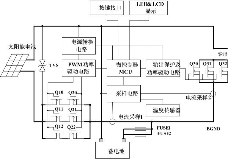
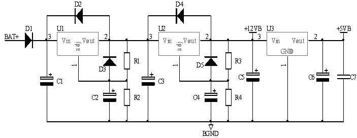
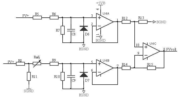
[0036] Solar charging control circuit of the present invention such as figure 1 As shown, it is used to control the solar battery to charge the battery and supply power to the load, including power conversion circuit, sampling circuit, microcontroller, PWM power drive circuit and output protection and power drive circuit, charging circuit and load circuit, and protection circuit, Man-machine interface circuit, LED and LCD display module and other modules.

[0037] The charging controller adopts a common positive circuit topology, the positive pole of the solar cell, the positive pole of the storage battery and the positive pole of the load are connected together; a transient voltage suppression diode TVS with lightning protection function is connected between the positive pole and the negative pole of the solar battery; The negative electrode is connected to the logic common g...


PUM


Abstract

The invention discloses a solar charging control circuit, which is used for controlling a solar cell to charge a storage battery and supply power to a load. The solar charging control circuit comprises a power switching circuit, a sampling circuit, a microcontroller, a pulse width modulation (PWM) power driving circuit, an output protection and power driving circuit, a charging loop and a load loop. The circuit overcomes the defects existing in the conventional solar charging controller and meets the requirements of application of large and medium-sized solar photovoltaic power stations according to characteristics and charging and discharging characteristics of a lead acid storage battery and power output characteristic of the solar cell; and the solar charging control circuit has the advantages of high capacity and efficiency, low cost, longer service life, more accurate battery management and more intelligent system.

Description

technical field [0001] The invention relates to the technical field of electric power, in particular to a solar charging control circuit. Background technique [0002] As a new energy source, solar energy is an inexhaustible renewable energy source that does not cause any pollution to the environment. It has become the first choice for governments to develop new energy sources that are pollution-free and sustainable. Solar cells can directly convert solar energy into electrical energy with high efficiency, without any pollution to the environment, and are a green power generation method. In the photovoltaic power generation system, the lead-acid battery and the solar charge controller are important components in the solar photovoltaic system. The battery can store the unstable and discontinuous electric energy emitted by the solar cell to ensure the stable output of the photovoltaic system. The quality of the charging controller not only determines the service life of the b...

Claims


Application Information

Patent Timeline
Patent Type & Authority Applications(China)
IPC IPC(8): H02J7/00H02N6/00H02S40/38
CPCY02E10/50Y02E70/30
Inventor 徐海波韩军良陈敬峰汪家荣
Owner EAST GRP CO LTD
Why Eureka
Try Eureka