

Device for zone-melting directional solidification of laser leviation and directional solidification method
A laser suspension zone melting and directional solidification technology, applied in the field of material processing engineering, can solve the problems of high cost and complex structure, and achieve the effect of reducing size, uniform distribution and good orientation
- Summary
- Abstract
- Description
- Claims
- Application Information
AI Technical Summary
Problems solved by technology
Method used
Image

Examples
Embodiment 1
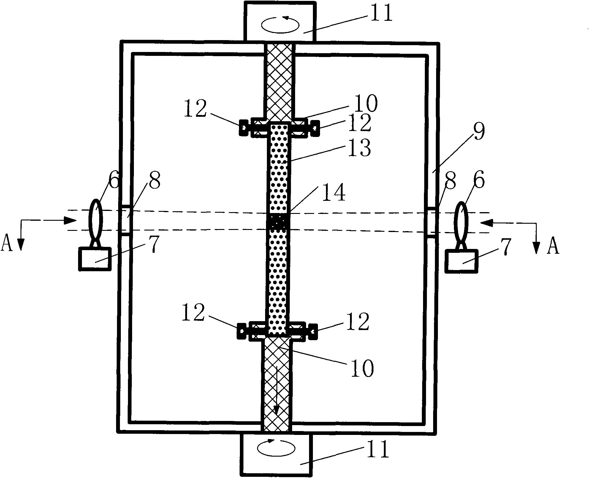
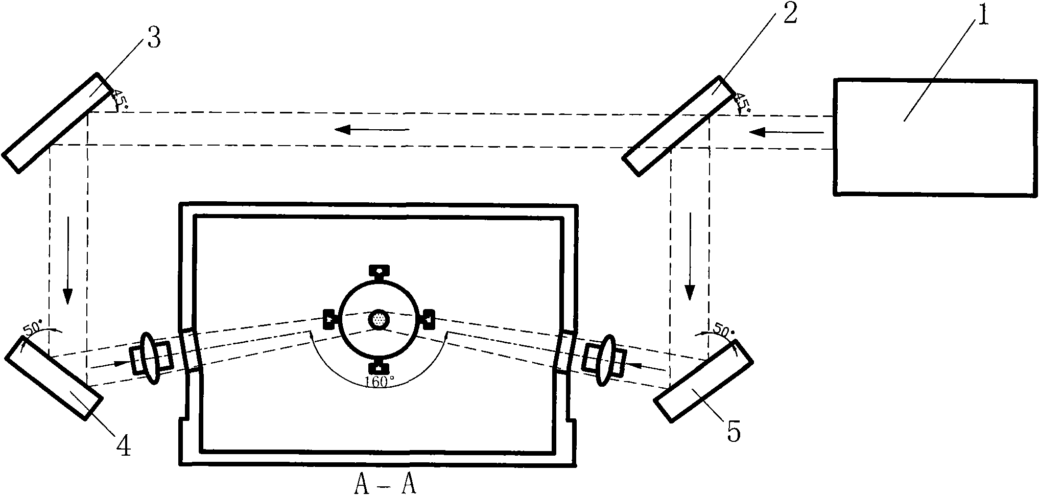
[0031]This embodiment is a device for melting and directional solidification of the laser suspension area, including a laser 1, a beam splitter 2, a reflector, two convex lenses 6, two flat lenses 8, a convex lens translation device 7, a vacuum chamber 9, and a pulling and rotating System 10 and two motor units 11 . In this embodiment, the three plane reflectors include the first reflector 3, the second reflector 4 and the third reflector 5, and the beam splitter 2, the first reflector 3, the second reflector 4 and the third reflector 5 are sequentially distributed on the outer periphery of the vacuum chamber 9 . The laser 1 is located on one side of the vacuum chamber 9 . Two circular flat lenses 8 are embedded respectively on the housings on both sides of the vacuum chamber 9; The two laser beams focused by the convex lens 6 enter the vacuum chamber 9 through the two flat lenses 8 and then fall on the axis of the drawing and rotating system 10 to realize the melting of the...
Embodiment 2
[0039] This example is a method for Al 2 o 3 The method of melting and directional solidification in the laser suspension zone of the / YAG oxide eutectic, the specific process includes the following steps:
[0040] The first step is to make the prefabricated body; Al 2 o 3 and Y 2 o 3 Two powders with a purity of 4N according to Al 2 o 3 / YAG eutectic components are mixed and put into a mortar, 10% PVA binder is added, the powder is mixed and ground by conventional methods until there is no agglomerated lump; 10 grams of the mixed powder is put into the cavity with a size of In a 68×10mm mold, the mold is clamped and pressurized at 25MPa, and the pressure is kept for 5 minutes, and the powder is pressed into a 68×10×5mm plate to form a blank of the preform; the blank of the pressed preform is sintered in the atmosphere , in order to increase the strength of the prefabricated body, the required sintering temperature and sintering time are determined according to differen...
Embodiment 3
[0043] This embodiment is a method for melting and directional solidification in the laser levitation region of oxide ternary hypereutectic crystal. The specific implementation process of this embodiment includes the following steps,
[0044] The first step is to make the prefabricated body; Al 2 o 3 , Y 2 o 3 and ZrO 2 Three kinds of powders with a purity of 4N are mixed according to molar percentage 64.6: 15.3: 20.1 and put into a mortar, add 10% PVA binder, and the powders are mixed and ground to no agglomerated lumps by conventional methods; 10 g Put the mixed powder into a mold with an inner cavity size of 68×10mm, close the mold and pressurize at 20MPa, hold the pressure for 7 minutes, and press the powder into a plate of 68×10×5mm to form a prefabricated blank; Next, sinter the blank of the pressed prefabricated body to increase the strength of the prefabricated body. The required sintering temperature and sintering time are determined according to different materi...
PUM
 Abstract
Description
Claims
Application Information