High-speed semiconductor device structure and forming method thereof

A device structure and semiconductor technology, applied in the fields of semiconductor devices, semiconductor/solid-state device manufacturing, electrical components, etc., can solve the problems of wasting layout area, reducing circuit operating speed, increasing device noise figure, etc., to improve noise characteristics, improve performance, the effect of reducing resistance

Inactive Publication Date: 2011-05-11
TSINGHUA UNIV
View PDF5 Cites 19 Cited by
  • Summary
  • Abstract
  • Description
  • Claims
  • Application Information

AI Technical Summary

Problems solved by technology

On the other hand, the hole mobility of bulk silicon is only about half of the electron mobility. In order to obtain the same driving capability, the channel width of the PMOSFET device is about twice that of the NMOSFET, which not only wastes the layout area, but also outputs parasitic The increase of the capacitance also reduces the working speed of the circuit, therefore, how to significantly improve the hole mobility of the PMOS device is particularly outstanding.
[0003] Furthermore, since the minimum noise factor of MOSFET devices is proportional to the gate resistance and source region resistance, in order to obtain high-speed, low-noise MOSFET devices, it is first required to reduce the gate length while maintaining or reducing the source and drain region resistance , and the reduction of the gate length will inevitably lead to the increase of the gate resistance, which will increase the noise figure of the device

Method used


Image

  • High-speed semiconductor device structure and forming method thereof
  • High-speed semiconductor device structure and forming method thereof
  • High-speed semiconductor device structure and forming method thereof

Examples


Embodiment Construction

[0028] Embodiments of the present invention are described in detail below, examples of which are shown in the drawings, wherein the same or similar reference numerals designate the same or similar elements or elements having the same or similar functions throughout. The embodiments described below by referring to the figures are exemplary only for explaining the present invention and should not be construed as limiting the present invention.

[0029] The following disclosure provides many different embodiments or examples for implementing different structures of the present invention. To simplify the disclosure of the present invention, components and arrangements of specific examples are described below. Of course, they are only examples and are not intended to limit the invention. Furthermore, the present invention may repeat reference numerals and / or letters in different instances. This repetition is for the purpose of simplicity and clarity and does not in itself indicat...


PUM


Abstract

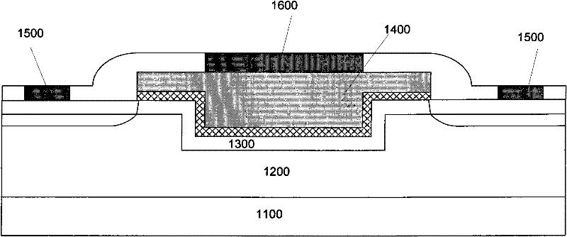
The invention provides a high-speed semiconductor device structure and a forming method thereof. The structure comprises a substrate, a Ge-containing strained layer formed on the substrate, an Si cap layer formed on the Ge-containing strained layer, a T-shaped gate structure formed on a part of the Si cap layer and covering the groove, and a source electrode and a drain electrode formed on the two sides of the T-shaped gate structure, wherein the Ge-containing strained layer has a groove. In the positive channel metal oxide semiconductor (PMOS) device structure of the embodiment of the invention, the two strained SiGe layers or Si layers with low Ge content on and below the strained SiGe layer or the strained Ge layer with high Ge content are arranged, so that a hole potential well can be formed in the strained SiGe layer or the strained Ge layer with high Ge content, the migration rate of the current carrier is increased and the performance of the semiconductor device is greatly improved.

Description

technical field [0001] The invention relates to the technical field of semiconductor manufacturing and design, in particular to a high-speed semiconductor device structure and a forming method thereof. Background technique [0002] For a long time, the feature size of Metal-Oxide-Semiconductor Field Effect Transistor (MOSFET) has been following the so-called Moore's law (Moore's law), and its working speed is getting faster and faster. However, for Si-based material itself As far as it is concerned, it is already close to the double limit of physics and technology. Therefore, various methods have been proposed in order to continuously improve the performance of MOSFET devices, and thus the development of MOSFET devices has entered a so-called post-Moore (More-Than-Moore) era. High-mobility channel engineering based on heterojunction structures, especially material systems such as Si-Ge and Si-C, is one of the effective technologies. The core idea of ​​this technology is to...

Claims


Application Information

Patent Timeline
Patent Type & Authority Applications(China)
IPC IPC(8): H01L29/78H01L29/06H01L29/08H01L29/423H01L21/336
Inventor 梁仁荣王巍王敬许军
Owner TSINGHUA UNIV
Why Eureka
Try Eureka