
All-silicon clock generator realized on basis of complementary metal oxide semiconductor (CMOS) process

A technology of clock generator and MOS tube, which is applied in the direction of instruments, pulse generation, electric pulse generation, etc., can solve the problems of temperature characteristics, process stability, poor power supply suppression ability, complex circuit, poor precision, etc., and achieve strong power supply suppression ability , The circuit structure is simple, the effect of reducing circuit cost and power consumption

Inactive Publication Date: 2011-05-18
SUZHOU R&D CENT OF NO 214 RES INST OF CHINA NORTH IND GRP
View PDF6 Cites 12 Cited by
  • Summary
  • Abstract
  • Description
  • Claims
  • Application Information

AI Technical Summary

Problems solved by technology

The above-mentioned self-excited oscillation is generally an RC oscillator or a ring oscillator. The RC oscillator has a simple structure and is easy to implement, but its accuracy is poor. It varies greatly with temperature and power supply voltage. It is generally used in clock accuracy In occasions with low requirements; in order to obtain better precision, the oscillator adopts a ring structure, which is usually composed of several delay circuits with a certain gain in a closed-loop form, but the disadvantage of this type of oscillator is that the circuit is more complicated and the temperature The characteristics, process stability and power supply suppression ability are also poor. This application is aimed at the improvement of the clock circuit of the ring oscillator

Method used


Image

  • All-silicon clock generator realized on basis of complementary metal oxide semiconductor (CMOS) process
  • All-silicon clock generator realized on basis of complementary metal oxide semiconductor (CMOS) process
  • All-silicon clock generator realized on basis of complementary metal oxide semiconductor (CMOS) process

Examples


Embodiment Construction

[0020] Below in conjunction with accompanying drawing, preferred specific embodiment of the present invention is described:

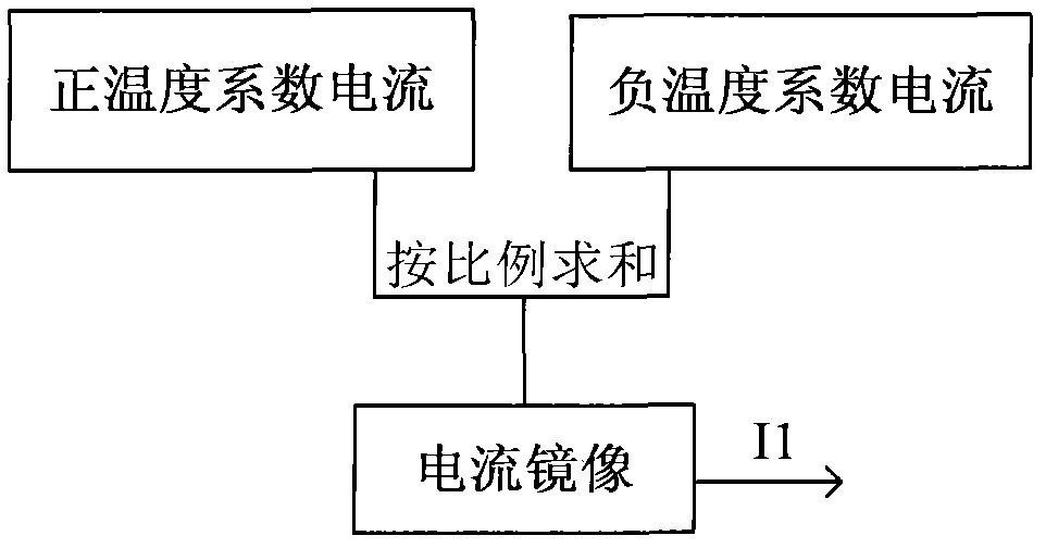
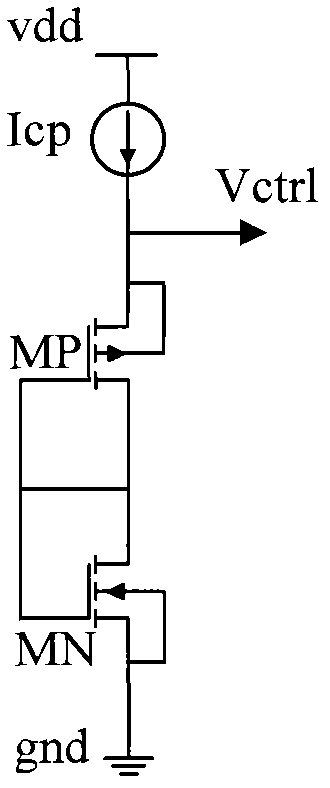
[0021] Such as figure 1 The all-silicon clock generator shown is sequentially connected by a temperature compensation reference source 11, a process compensation circuit 12, a V-I conversion circuit 13, a ring oscillator 14, and a shaping circuit 15. The temperature compensation reference source 11 is used to receive input power supply voltage, and temperature-compensate the input voltage according to the change of external temperature to output a stable voltage or current signal to the process compensation circuit 12, and the process compensation circuit 12 receives the voltage or current signal output by the reference source and generates the circuit according to the entire clock Process deviation is compensated to output a compensated control voltage Vctrl, and the control voltage Vctrl is output to the V-I conversion circuit 13 to be converted into ...


PUM


Abstract

The invention relates to an all-silicon clock generator realized on the basis of a complementary metal oxide semiconductor (CMOS) process. The all-silicon clock generator comprises a temperature compensation current source, a process compensation circuit, a V-I conversion circuit, a loop oscillating circuit and a shaping circuit the output ends of which are sequentially connected, wherein the temperature stabilizing current source is used for providing current after temperature compensation; the process compensation circuit is used for providing voltage for reducing the deviation of the CMOS process; the V-I conversion circuit is used for converting the compensated voltage to current output; the loop oscillating circuit generates clock signals with the corresponding frequency according tothe magnitude of the received current; and the shaping circuit is used for shaping the clock signals and outputting after frequency division. The invention adopts the temperature and process compensation circuits, thus ensuring that the CMOS clock circuit has favorable temperature and process stabilities and also has stronger power-supply rejection capacity. Besides, the circuit structure is simple, and the clock accuracy is high, so that the CMOS clock circuit can be substituted for a quartz crystal oscillator, a ceramic resonator and other circuits and used as a clock source.

Description

technical field [0001] The invention relates to a clock generator, in particular to a clock generator based on CMOS technology. Background technique [0002] In various electronic systems, the clock signal is an indispensable reference signal. It has a wide range of applications from clock generation in microprocessors to carrier synthesis in cellular phones, as well as measurement, remote control and automatic control. Usually, the clock signal in the electronic system generates a reference clock signal through a quartz crystal oscillator set outside the electronic system, and then the phase-locked loop in the system outputs a higher frequency clock signal for the internal circuit based on the reference clock signal. use. However, although a more accurate clock signal can be generated by using a quartz crystal oscillator to generate a clock signal, this method requires pins to receive the reference clock signal, which will cost a higher pin cost. [0003] With the develop...

Claims


Application Information

Patent Timeline
Patent Type & Authority Applications(China)
IPC IPC(8): H03K3/011G05F1/567
Inventor 龙善丽唐兴刚贺克军张紫乾吕江平白涛
Owner SUZHOU R&D CENT OF NO 214 RES INST OF CHINA NORTH IND GRP
Learn More