Eddy current device

The technology of a vortex chamber and a vortex wheel, which is applied in the field of vortex devices, can solve the problems of difficult to handle by-products, unsatisfactory purification effect, and incomplete purification, and achieve the effect of low use cost, low maintenance cost, and good pressurization effect.

Inactive Publication Date: 2011-06-08
陈久斌
View PDF0 Cites 1 Cited by
  • Summary
  • Abstract
  • Description
  • Claims
  • Application Information

AI Technical Summary

Problems solved by technology

[0005] Existing desulfurization and denitrification tail gas purification equipment is too expensive, consumes too much energy, the purification effect is not ideal, can not be completely purified, and there are defects such as difficult to handle by-products and secondary pollution.

Method used


Image

  • Eddy current device
  • Eddy current device
  • Eddy current device

Examples


Embodiment Construction

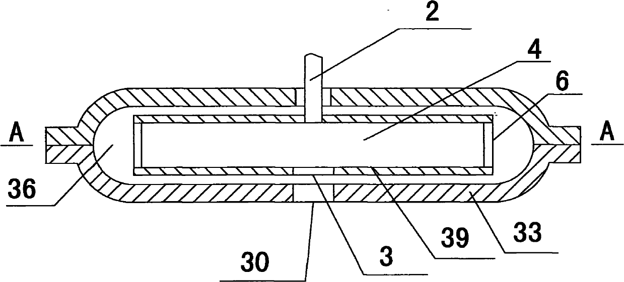
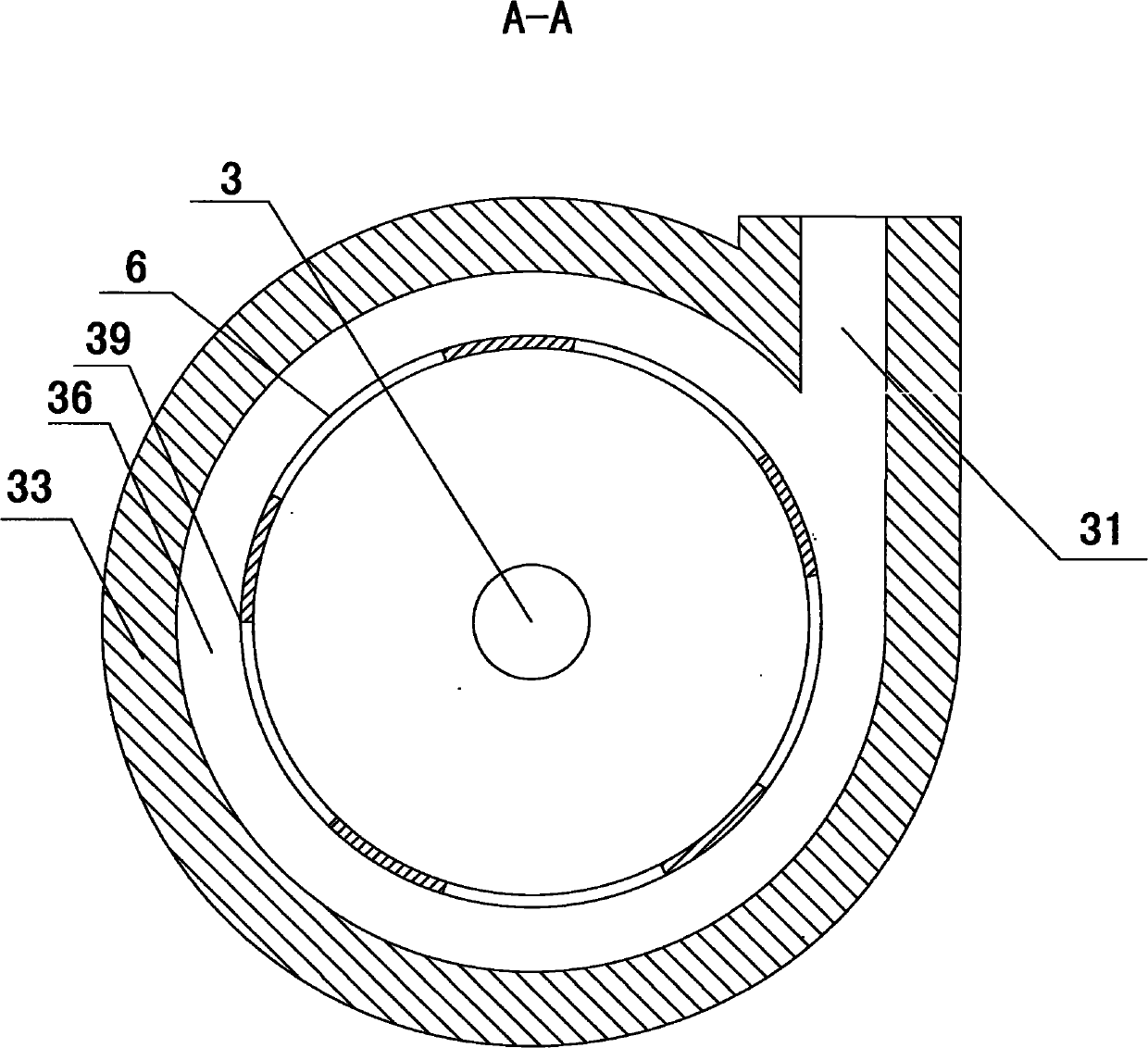
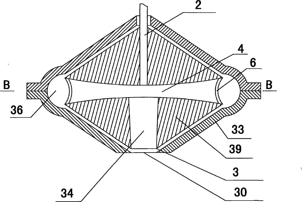
[0048] The main structure of the vortex generator of the present invention includes a housing 33 and a transmission shaft 2. A housing cavity 36 is provided in the housing 33. The transmission shaft 2 is installed in the housing 33. A vortex wheel 39 is arranged in the housing cavity 36. The transmission shaft 2 and the vortex wheel 39 connection, the vortex wheel 39 is provided with a vortex chamber 4, the vortex chamber inlet 3 is provided in the middle of the vortex chamber 4, the vortex chamber outlet 6 is provided on the periphery of the vortex chamber 4, the housing cavity 36 is provided with a housing cavity inlet 30, the vortex chamber inlet 3 and the housing cavity inlet 30 Correspondingly, the casing cavity 36 is provided with a casing cavity outlet 31 .

[0049] The scope of the casing 33 includes the base, the casing, and the power unit, and each part can be collectively referred to as a casing. The housing can also be integrated with the power device to form an in...


PUM


Abstract

The invention discloses an eddy current supercharger. The eddy current supercharger comprises a shell and a transmission shaft, wherein a shell cavity is formed in the shell; the transmission shaft is arranged in the shell; an eddy current wheel is arranged in the shell cavity; the transmission shaft is connected with the eddy current wheel in which an eddy current chamber is formed; the middle part of the eddy current chamber is provided with an eddy current chamber inlet; the periphery of the eddy current chamber is provided with an eddy current chamber outlet; the shell cavity is provided with a shell cavity inlet; the eddy current chamber inlet is formed opposite to the shell cavity inlet; and the shell cavity is provided with a shell cavity outlet. In the eddy current supercharger, completely new supercharging principle and method are adopted, circular motion and fluid motion can be fully utilized, fluid is automatically sucked into an eddy current from an eddy current central region by using the eddy current of which the rotation speed gradually increases from the center to the periphery, super-high suction is produced by using the center of the eddy current, and super-high pressure is produced by using the periphery of the eddy current. The eddy current supercharger can be widely used in the fields such as fluid pressurizing, fluid conveying, air suction and the like, can be used as a water pump, a fan, a compressor, a vacuum machine and the like, and can also be used as spray equipment, a nanomaterial atomizer, purification equipment for processing carbon dioxide, sulfur oxide and nitric oxide, a special reactor, an air conditioner and the like.

Description

technical field [0001] The invention relates to the fields of booster equipment, suction equipment, spray equipment, reactor equipment, and exhaust gas purification equipment, in particular to a vortex device. It can be widely used in the fields of fluid pressurization, transportation, suction and the like. It can be used as water pump, booster pump, vacuum pump, self-priming pump, mud pump, dredging pump, air pump, fan, air compressor, vacuum cleaner, suction equipment, vacuum machine, etc. It can generate ultra-high pressure and ultra-high suction. Also works as a nebuliser, producing a high-pressure, ultra-fine mist. It can also be used as a reactor, which can form a special reaction condition environment in the vortex to complete special chemical and physical reactions. It can also be used as tail gas purification equipment for desulfurization and denitrification, etc. It can completely separate and treat carbon dioxide, nitrogen oxides, and sulfur oxides, and can separa...

Claims


Application Information

Patent Timeline
IPC IPC(8): F15B3/00F04D1/02F04D17/02F04D29/42F04D29/18F04D29/26F04D29/08
Inventor 陈久斌
Owner 陈久斌
Why Eureka
Try Eureka