
Laminated composite solar battery

A solar cell and composite technology, applied in the field of solar energy, can solve the problems of not making good use of the advantages of the laminated structure, achieve good photoelectric conversion performance, balance production costs, and improve photoelectric conversion efficiency

Inactive Publication Date: 2011-06-15
ZHONGSHAN IKER DIGITAL TECH
View PDF7 Cites 7 Cited by
  • Summary
  • Abstract
  • Description
  • Claims
  • Application Information

AI Technical Summary

Problems solved by technology

This patent adopts a stacked structure, and the realized solar cell is an organic solar cell. Since the advantages of the stacked structure are not well utilized, the energy conversion efficiency of the solar cell is as high as 3.36%, which is a relatively low level.

Method used


Image

  • Laminated composite solar battery
  • Laminated composite solar battery
  • Laminated composite solar battery

Examples


Embodiment 1

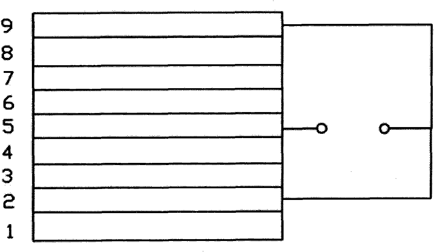
[0028] refer to figure 1 , the inventive solution of this embodiment, the tandem composite solar cell is composed of nine different functional layers. The sequence is a transparent substrate 1, a cathode layer 2, a polar organic layer 3, a first photosensitive layer 4, a semitransparent anode layer 5, a P-type semiconductor layer 6, a P-N transition layer 7, an N-type semiconductor layer 8, and a transparent conductive layer 9; in:

[0029] The transparent substrate 1 is preferably made of glass or plastic; the thickness of the transparent substrate 1 is not particularly limited, and can be appropriately adjusted according to actual needs, but the substrate must have good light transmission performance.

[0030] Cathode layer 2: its material is preferably indium tin oxide or tin oxide; the cathode layer 2 can be formed by any conventional method, such as vapor deposition, sputtering, etc.; the thickness of the cathode layer 2 is between 150-600 nm.

[0031] Polar organic lay...

Embodiment 2

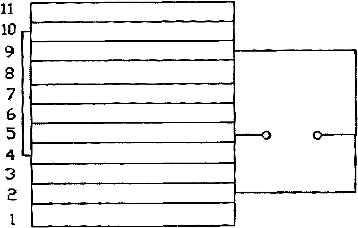
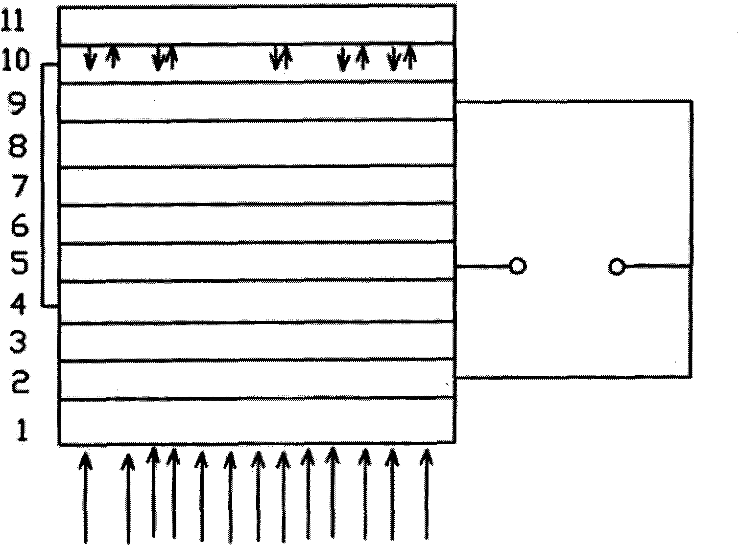
[0040] Embodiment 2 is further optimized on the existing basis of Embodiment 1. The difference is that: reference figure 2 with 3 The semi-transparent anode layer 5 of the laminated composite solar cell also has a second photosensitive layer 10, and the second photosensitive layer 10 and its formation method and thickness can be implemented with reference to the first photosensitive layer 4; the second photosensitive layer 10 also has a non-conductive light-reflective layer. Layer 12, the material can be selected to add high refractive index glass bead reflective paint, which is formed by spraying and other methods. The second photosensitive layer 10 is connected to the first photosensitive layer 4 across layers through a conductor (such as a silver film). refer to image 3 , the afterglow of the sun reaches the non-conductive reflective layer 12 and is reflected, further stimulating the photoelectric induction of the second photosensitive layer 10; the second photosensiti...


PUM


Abstract

The invention discloses a laminated composite solar battery, which consists of eleven different functional layers, namely a transparent substrate, a cathode layer, a polar organic layer, a first light sensitive layer, a semi-transparent anode layer, a P-type semiconductor layer, a P-N transition layer, a N-type semiconductor layer, a transparent conductive layer, a second light sensitive layer and a non-conductive light reflecting layer, wherein the transparent anode layer is reticular; a plurality of ways, including the lamination of an organic solar battery and an inorganic solar battery, are simultaneously adopted for enhancing the photoelectric conversion efficiency of battery, thus the solar energy is fully utilized, the skillful lamination of the organic and inorganic solar batteries is realized, and production costs are equalized while the maximal photoelectric conversion efficiency is exerted; the structure of the second light sensitive layer and the non-conductive light reflecting layer is adopted for repeatedly making use of the sunlight, so secondary photoelectric conversion of the organic solar battery is reinforced and the conversion efficiency of the overall battery can reach over 35%.

Description

technical field [0001] The invention belongs to the technical field of solar energy, and in particular relates to a solar cell which adopts a stacked structure to improve the photoelectric conversion efficiency of solar energy. Background technique [0002] Solar energy is an ideal new energy source. It has the advantages of being inexhaustible, and it is also a clean energy source without any environmental pollution. Among the effective use of solar energy, solar photoelectric conversion is the most developed in recent years. Fastest and most dynamic research field. At present, solar cells are mainly divided into crystalline silicon solar cells, inorganic thin film solar cells, organic solar cells and dye-sensitized solar cells. Among them, the photoelectric conversion efficiency of crystalline silicon solar cells is the highest, reaching 18%. Inorganic thin-film solar cells are below 11%, while organic solar cells are 6%-7%. However, organic solar cells have the character...

Claims


Application Information

Patent Timeline
Patent Type & Authority Applications(China)
IPC IPC(8): H01L51/42H01L51/44
CPCY02E10/549Y02E10/50
Inventor 叶灿才卢林发
Owner ZHONGSHAN IKER DIGITAL TECH
Learn More