Method and system for measuring position compensation angles of permanent magnet synchronous motor rotor

A permanent magnet synchronous motor, rotor position technology, applied in the field of control, can solve the problems of small rotor position jitter, complex realization, obvious small rotor position jitter, etc.

Active Publication Date: 2011-06-15
北京和利时电机技术有限公司
View PDF6 Cites 40 Cited by
  • Summary
  • Abstract
  • Description
  • Claims
  • Application Information

AI Technical Summary

Problems solved by technology

[0019] The forced current vector method requires a current sensor, which is complex to implement, and the current closed loop will cause tiny rotor position to jitter
Especi...

Method used


Image

  • Method and system for measuring position compensation angles of permanent magnet synchronous motor rotor
  • Method and system for measuring position compensation angles of permanent magnet synchronous motor rotor
  • Method and system for measuring position compensation angles of permanent magnet synchronous motor rotor

Examples


Embodiment 1

[0063] Embodiment 1, a method for measuring the rotor position compensation angle of a permanent magnet synchronous motor, comprising:

[0064] Set Forced Field Orientation Angle Let d-axis voltage component command value Input the q-axis voltage component command value that can make the permanent magnet synchronous motor enter the zero-speed lock shaft state

[0065] According to the orientation angle of the forced magnetic field Will and The voltage vector is obtained by inverse PARK transformation and

[0066] Convert the voltage vector and Generate the power device pulse width signal required by the voltage source inverter through the space voltage vector pulse width modulation algorithm SVPWM;

[0067] The voltage source inverter drives the permanent magnet synchronous motor to rotate to position; can be, but not limited to, drive a permanent magnet synchronous motor to rotate in a manner similar to a stepper motor stable position;

[0068] Obtain...

Embodiment 2

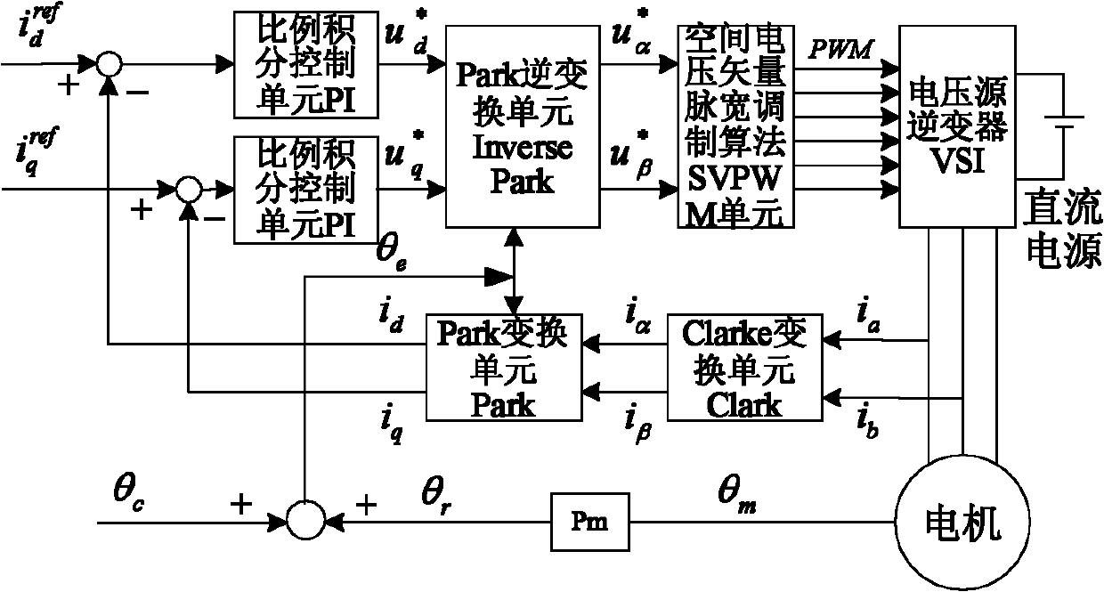
[0092] Embodiment 2, a permanent magnet synchronous motor rotor position compensation angle measuring device, such as Figure 4 shown, including:

[0093] The input unit is used to input the q-axis voltage component command value that can make the permanent magnet synchronous motor enter the zero-speed shaft-lock state and the d-axis voltage component command value equal to 0

[0094] Inverse Park Transformation Inverse Park unit for orientation angles according to a pre-set forced magnetic field right and Perform Park inverse transformation to get and

[0095] Space Voltage Vector Pulse Width Modulation Algorithm SVPWM unit for the voltage vector according to the and Using space voltage vector pulse width modulation algorithm to generate power device pulse width signal;

[0096] The voltage source inverter VSI, by the voltage u dc The DC bus power supply is used to generate the three-phase winding current i according to the pulse width signal of the power ...


PUM


Abstract

The invention provides a method and device for measuring position compensation angles of a permanent magnet synchronous motor rotor, wherein the method comprises the following steps: setting a forcible magnetic field directional angle Theta Force; setting component instruction value of a d shaft voltage as u*d=0; inputting the component instruction value u*q of a q shaft voltage which can enable the permanent magnet synchronous motor to enter into a zero speed shaft locking state; according to the forcible magnetic field directional angle Theta Force, obtaining voltage vectors by virtue of PARK inverse transformation of u*d and u*q; generating a power device pulse-width signal needed by a voltage source inverter by a space vector pulse width modulation (SVPWM) algorithm; driving the permanent magnet synchronous motor to rote to a position of ThetaForcee+90 DEG by the voltage source inverter; obtaining the angle Theta xr read by an absolute encoder mounted on the rotor; and calculating the compensation angle that Theta c= Theta Force+ 90 DEG-Theta xr. The method provided by the invention can be simply, conveniently and easily realized; a current sensor is unnecessary to work, and the flitter is not existed during initial location.

Description

technical field [0001] The invention relates to the control field, in particular to a method and system for measuring the rotor position compensation angle of a permanent magnet synchronous motor. Background technique [0002] With the rapid development of rare earth permanent magnet materials, power electronics technology and motor control theory, permanent magnet synchronous motor PMSM has the advantages of high torque / inertia ratio, high power density, high efficiency, firmness and good maintainability. Textile, chemical fiber, CNC machine tools, industrial robots, aerospace and other fields have been increasingly widely used. [0003] When the permanent magnet synchronous motor control system adopts vector control, precise rotor position signals are required to achieve field-oriented control. When the initial position of the rotor permanent magnet direct axis is wrong, it will cause the wrong orientation of the stator current vector, which will lead to a decrease in the ...

Claims


Application Information

Patent Timeline
IPC IPC(8): H02P6/16H02P21/14H02P21/18
Inventor 韩利夏燕兰姚宏武将丁伟
Owner 北京和利时电机技术有限公司
Why Eureka
Try Eureka