Heavy oil catalytic cracking method and device by double-area coupling and catalyst tandem

A heavy oil catalysis and catalyst technology, applied in the field of petroleum processing, can solve the problems such as the deterioration of catalytic cracking raw materials, and achieve the effects of solving the increasingly deteriorated quality, improving the yield and liquid yield, and improving the average activity

Inactive Publication Date: 2011-06-22
CHINA UNIV OF PETROLEUM (BEIJING)
View PDF2 Cites 12 Cited by
  • Summary
  • Abstract
  • Description
  • Claims
  • Application Information

AI Technical Summary

Problems solved by technology

[0008] The main technical problem to be solved by the present invention is to provide a heavy oil catalytic cracking method using dual-zone coupling and catalyst series in view of the increasingly inferior quality of catalytic cracking raw materials in refineries. Dist

Method used


Image

  • Heavy oil catalytic cracking method and device by double-area coupling and catalyst tandem
  • Heavy oil catalytic cracking method and device by double-area coupling and catalyst tandem
  • Heavy oil catalytic cracking method and device by double-area coupling and catalyst tandem

Examples


Embodiment 1

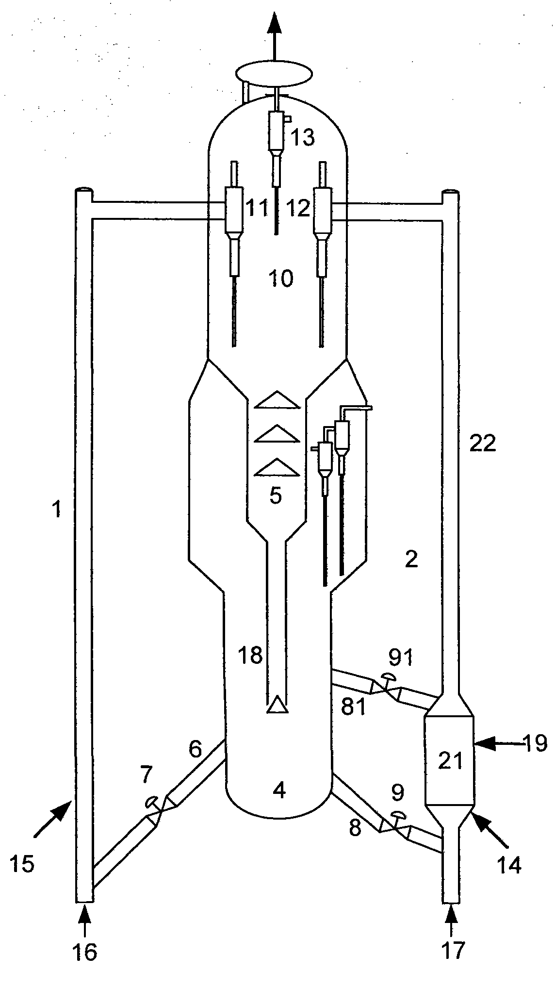
[0043] see figure 1 The flow process, in the catalyst regenerator 4 of the heavy oil catalytic cracking reaction unit (the present invention is the coaxial catalytic cracking unit that the settler and the regenerator are coaxially arranged as an example, and the settler can also be used in the production on the upper part of the riser reactor However, a conventional riser reactor 1 is arranged next to the high and low side-by-side catalytic cracking units arranged in parallel with the regenerator, and a part of the high-temperature regenerated catalyst in the catalyst regenerator 4 passes through the catalyst delivery pipe 6 and its The regenerated catalyst slide valve 7 on the top enters the riser reactor 1 and flows upward under the lifting action of the lifting gas 16 and high-quality catalytic feedstock oil 15 (the feedstock oil is distilled and cut in advance, and the residual carbon value is less than 2wt%. Embodiment same) contact reaction, be 100~300 ℃ and opening degr...

Embodiment 2

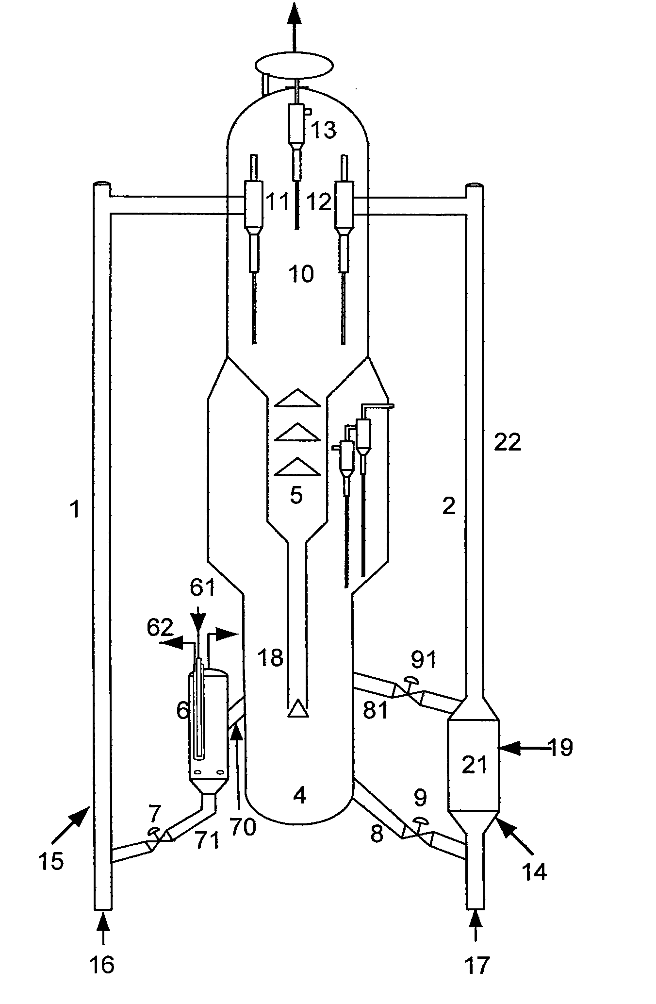
[0046] see figure 2 In the flow chart shown, a conventional riser reactor 1 and a regenerated catalyst cooler 6 are arranged next to the catalyst regenerator 4 of the heavy oil catalytic cracking reaction unit, and a part of the high-temperature regenerated catalyst in the catalyst regenerator 4 enters the regenerated agent for cooling through the catalyst delivery pipe 70 6, the cooling medium enters through the inlet 61 and flows out through the outlet 62, and the temperature of the regenerated catalyst entering the cooler 6 is cooled from 680 to 710°C to 580 to 670°C, and the cooled catalyst passes through the regenerated inclined pipe 71 and The regenerated catalyst slide valve 7 enters the riser reactor 1, and flows upward under the lifting action of the lifting gas 16 to contact and react with the high-quality catalytic raw material oil 15. The reaction conditions of the riser reactor 1 are: the preheating temperature of the raw material is 100-300°C, The temperature of...

Embodiment 3

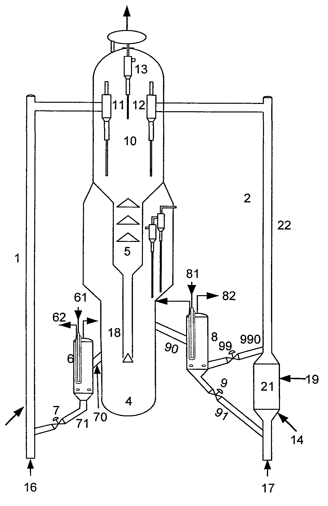
[0050] see image 3 As shown in the flow process, a conventional riser reactor 1 and a regenerated catalyst cooler 6 are arranged next to the catalyst regenerator 4 of the heavy oil catalytic cracking reaction unit, and a part of the high-temperature catalyst in the catalyst regenerator 4 enters the regenerated agent cooler 6 through the catalyst delivery pipe 70 , the cooling medium enters through the inlet 61 and flows out through the outlet 62, and the temperature of the regenerated catalyst entering the cooler 6 is cooled from 680 to 710°C to 580 to 670°C, and the cooled catalyst passes through the regenerated inclined pipe 71 and the regenerated catalyst The sliding valve 7 enters the riser reactor 1, and flows upward under the lifting action of the lifting gas 16 to contact and react with the high-quality catalytic raw material oil 15. The temperature of the regenerated catalyst before the tube reactor 1 is 580-670°C, the reaction temperature is 460-520°C, the catalyst-o...


PUM


Abstract

The invention provides a method and a device for realizing catalytic cracking of heavy oil by a double-area coupling and catalyst tandem process, and belongs to the technical field of petroleum processing. According to difference of reaction characteristics of heavy oil catalytic cracking materials, the heavy oil catalytic cracking materials are divided into quality catalytic materials and inferior catalytic materials according to carbon residue values; and the quality catalytic materials and the inferior catalytic materials respectively enter different reaction areas in a catalytic cracking reaction system for catalytic cracking reaction. For the quality catalytic materials, a conventional riser reactor is utilized; for the inferior catalytic materials, a turbulent bed or fast bed and transport bed combined reactor is utilized, and the catalyst tandem process is adopted, so that the two parts of materials adopt respectively optimized reaction conditions in respective independent reaction areas provided by different-structure reactors; and the catalyst and oil contact temperature difference is reduced and a large catalyst-oil ratio is achieved by arranging a catalyst cooler, the problem that the catalyst in a reaction area for the inferior materials is severe in coking, quick in deactivation and low in later activity is improved and the light oil yield and the integral liquid yield are obviously improved.

Description

technical field [0001] The invention relates to a production process for improving the conversion efficiency of catalytic cracking reaction of heavy oil, especially the production process of light oil yield and liquid yield, and especially provides a method and device for realizing catalytic cracking of heavy oil by using dual-zone coupling and catalyst series process, The invention belongs to the technical field of petroleum processing. Background technique [0002] Catalytic cracking process is the main means of lightening heavy oil and an important production process of light oil products such as liquefied petroleum gas, gasoline and diesel. The traditional catalytic cracking feedstock is mainly vacuum distillate oil. Due to the growing demand for light oil and the increase in crude oil prices, catalytic cracking technology is used to process heavy feedstock oil, such as atmospheric heavy oil, vacuum residue and deasphalting residue Oil to improve economic efficiency has...

Claims


Application Information

Patent Timeline
IPC IPC(8): C10G51/06
Inventor 高金森王刚白跃华张兆前徐春明高浩华张冬超文尧顺蓝兴英白光
Owner CHINA UNIV OF PETROLEUM (BEIJING)
Why Eureka
Try Eureka