Frequency-scanning antenna array based on CRLH-TL

A left-handed composite antenna array technology, applied in the microwave field, can solve the problems of reducing side lobe level, poor low frequency characteristics, small scanning angle, etc., to achieve the effect of reducing side lobe level, small leaky wave radiation, and large scanning angle

Inactive Publication Date: 2011-07-06
XI AN JIAOTONG UNIV
View PDF1 Cites 16 Cited by
  • Summary
  • Abstract
  • Description
  • Claims
  • Application Information

AI Technical Summary

Problems solved by technology

[0006] The technical purpose of the present invention: in order to solve the problems of large volume, large insertion loss and small scanning angle of the traditional slow wave structure frequency scanning antenna array; also in order to solve the problem of using interdigitated capacitance to form a left and right hand transmission line str

Method used


Image

  • Frequency-scanning antenna array based on CRLH-TL
  • Frequency-scanning antenna array based on CRLH-TL
  • Frequency-scanning antenna array based on CRLH-TL

Examples


Embodiment Construction

[0032] The embodiments of the present invention are described in detail below in conjunction with the accompanying drawings: the present embodiment is implemented on the premise of the technical solution of the present invention, and detailed implementation methods and specific operating procedures are provided, but the protection scope of the present invention is not limited to the following the embodiment.

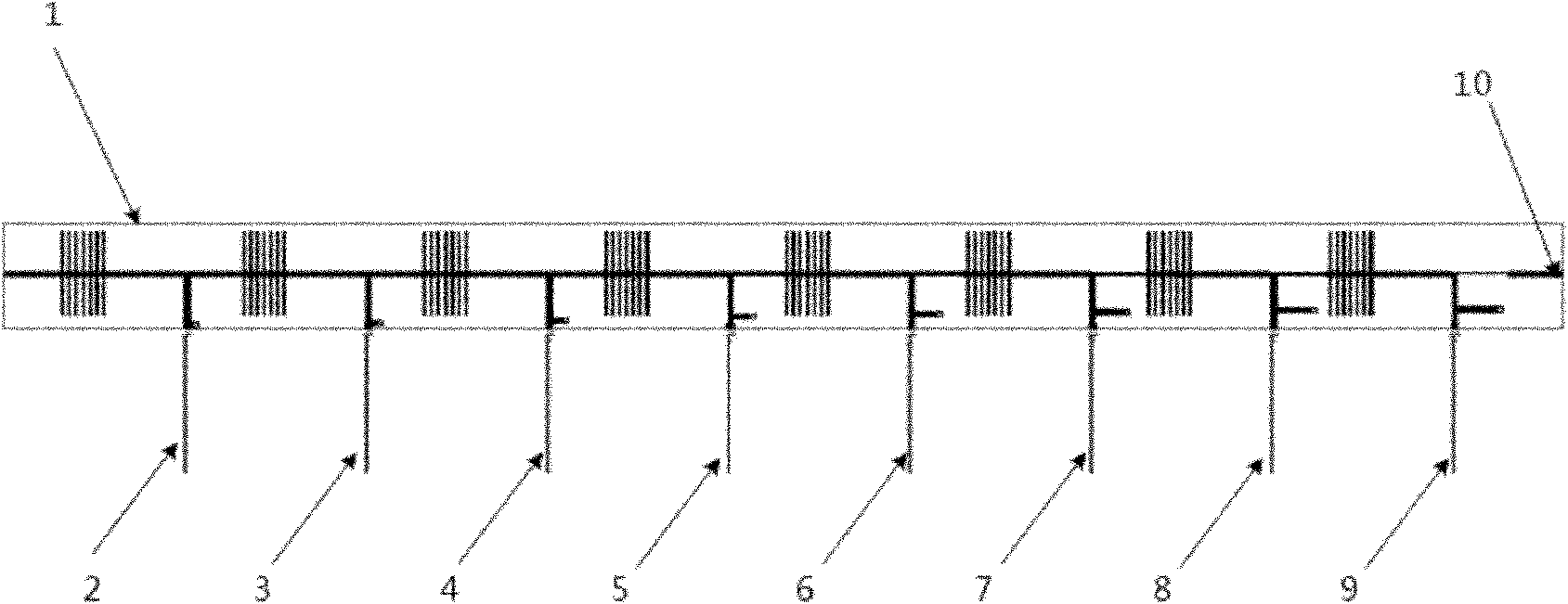
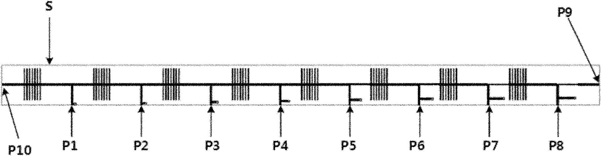
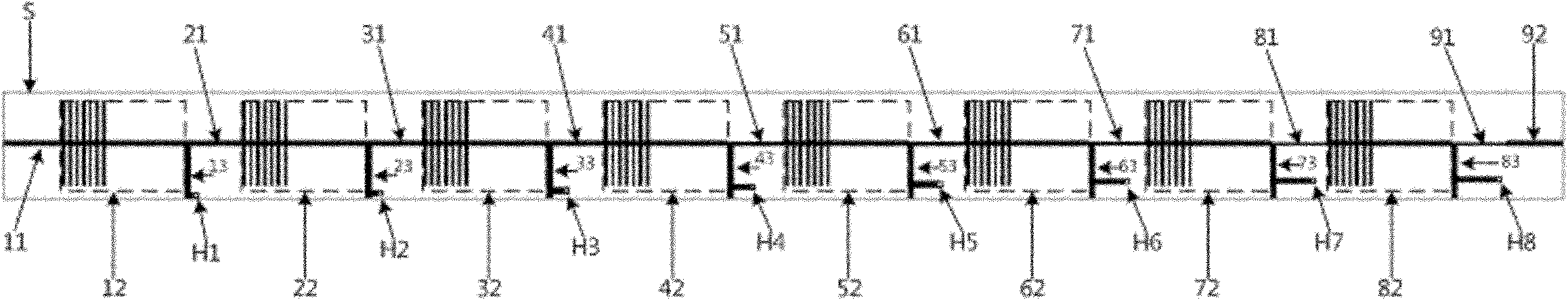
[0033] An embodiment of the invention is a frequency-swept antenna array, such as figure 1 , figure 2 , image 3 , Figure 4 , Figure 5 , Figure 6 , Figure 7 As shown, this embodiment includes a feeding network 1 , eight element antennas 2 to 9 , and a matching load 10 .

[0034] Wherein, the feeding network includes an input port P10, nine output ports P1-P9, a dielectric substrate S, a matching network, a coupling line, a left-handed composite transmission line and a grounding plate. The ground plate is printed on the lower surface of the dielectric substrat...


PUM


Abstract

The invention provides a frequency-scanning antenna array based on a CRLH-TL (composite right /left -handed transmission line) and belongs to the field of microwave technology. The antenna array comprises a feed network and unit antennas, wherein the feed network comprises CRLH-TLs and a matching network, and both the CRLH-TLs and the matching network are made of copper-clad media plates; a coupled line, lambada/4 impedance transformers and single stubs are molded on a metal layer on the upper surface of each media plate and connected with a grounding plate on the lower surface of each media plate through metallized through holes. Every unit antenna is a micro-strip feed type quasi-yagi antenna made of a copper-clad media plate, and comprises a half-wave dipole antenna and two directors. The frequency-scanning antenna array realizes the CRLH-TL structure through the coupled line and can greatly reduce the leaky wave radiation in a feed network and increase the scanning range of the antenna array. Since non-uniform feeding to the unit antennas is realized through the matching network, the antenna array is endowed with the characteristics of high gain and low sidelobe.

Description

technical field [0001] The invention belongs to the field of microwave technology, and relates to a frequency-sweeping antenna array, in particular to a low-leakage, low-sidelobe frequency-sweeping antenna array based on a left-handed left-hand composite transmission line of coupled lines. Background technique [0002] Left-Hand Material, also known as double negative medium or negative refractive index material, is a kind of material with both negative permittivity and negative magnetic permeability in a certain frequency band. The idea of ​​left-handed materials was first proposed by the former Soviet Union V.G. Veselago (V.G. Veselago, The electrodynamics of substances with simultaneously negative value of ε and μ. Soviet Physics, 1968, 10(4): 509-514), when electromagnetic waves propagate in left-handed materials , the electric field, magnetic field and wave vector satisfy the left-handed spiral relationship, and the phase velocity is opposite to the energy flow directio...

Claims


Application Information

Patent Timeline
IPC IPC(8): H01Q21/10H01Q21/00H01Q19/30
Inventor 张安学李晨蒋延生徐卓李波
Owner XI AN JIAOTONG UNIV
Why Eureka
Try Eureka