
Polymer-based magnetodielectric material and process thereof for manufacturing electronic device

A technology of magnetic dielectrics and polymers, which is used in electrical components, waveguide-type devices, inorganic materials, etc.

Inactive Publication Date: 2011-07-20
深圳市微航磁电技术有限公司
View PDF19 Cites 10 Cited by
  • Summary
  • Abstract
  • Description
  • Claims
  • Application Information

AI Technical Summary

Problems solved by technology

[0033] (2) Left-handed effect materials and photonic crystal materials are added to polymer substrates to realize the simultaneous use of left-handed materials in device design and solve related manufacturing process problems

Method used


Image

  • Polymer-based magnetodielectric material and process thereof for manufacturing electronic device
  • Polymer-based magnetodielectric material and process thereof for manufacturing electronic device
  • Polymer-based magnetodielectric material and process thereof for manufacturing electronic device

Examples


specific Embodiment approach

[0055] The invention achieves the purpose of the invention from the aspects of antenna space structure design, material selection, manufacturing process, device performance guarantee, etc. The specific implementation method is:

[0056] Structural design:

[0057] Use polymer substrate surface winding or selective metallization technology, and then cover the resin process; the specific structure sequence is:

[0058] Step 1: Injection-molding regular-shaped chip or rod-shaped antenna inner tubes with polymer magnetic dielectric materials that have been kneaded, and metal terminals can be embedded in the injection molding process;

[0059] Step 2: Wind metal wires or print conductive ink, paint, or laser-induced metallization wiring on the inner tube of the antenna; the metallized wires are in good contact with the embedded metal terminals.

[0060] Step 3: Encapsulate the device with resin on the basis of the above step 2.

[0061] Material Design:

[0062] Polymer raw mate...

Embodiment 1

[0077] Figure 6 Shown is the structural diagram of the chip antenna of the embodiment of the present invention, the antenna inner tube (6-1) is made by using the polymer magnetic dielectric material and the injection molding process described in the present invention; the metal terminal (6-4) is embedded in the injection molding; Wind the metal wire (6-2) on the surface of the antenna inner tube, and weld one end of the metal wire (6-2) to the metal terminal (6-4); repackage the resin (6-3)

Embodiment 2

[0079] Figure 7 It is a schematic diagram of the appearance of the rod antenna of the example of the present invention,

[0080] Among them, 7-1 is the metal terminal at the bottom, and 7-2 is the metal terminal at the side;


PUM

PropertyMeasurementUnit
Thicknessaaaaaaaaaa

Abstract

The invention relates to synthesis of a polymer-based magnetodielectric material and a process for manufacturing an electronic device, one of high-density polyethylene, polypropylene, polyfluortetraethylene, syndiotactic polystyrene and the like with low electromagnetic loss is specifically adopted, a surfactant, a compatibilizer, soft magnetic material powder with a certain particle size and magnetic loss, dielectric material powder with a certain particle size and dielectric loss, a left-hand effect material or photonic crystal material and other specific functional materials are added, high-temperature melting and mixing are performed in an internal mixer, cooling and crushing are further performed, granulation is performed for preparing modified plastics, and the electronic device is further manufactured according to the following flow path and process: injecting into the shape of a sheet or a rod, and further performing surface selective metallization, ultraviolet curing or hot-melt adhesive low-pressure injection packaging. The device manufactured by the material and the process is mainly used for miniaturized antennas. The device has a series of characteristics of wide frequency band, low impedance, deviation of a working frequency to low frequency band, special frequency selectivity and the like.

Description

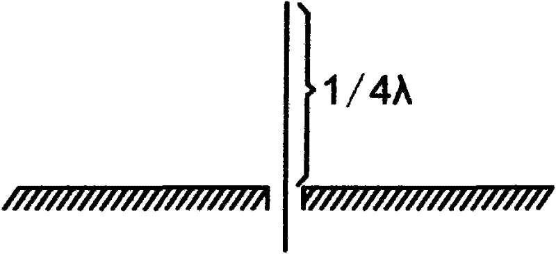
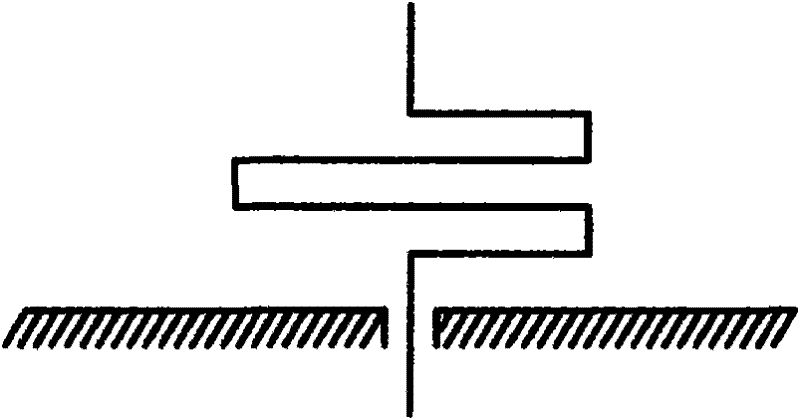
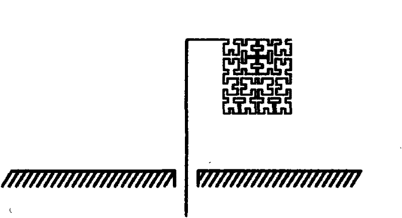
technical field [0001] The invention relates to an electronic material and a process for manufacturing the device. The manufactured electronic device is mainly a miniature antenna, and the antenna is used in the fields of wireless local area network, short-distance wireless communication, personal mobile communication, digital mobile TV and the like. Background technique [0002] Antenna is a very important device in wireless transceiver equipment, and its index directly affects product performance. The small size antennas in use now are basically from such as figure 1 The quarter-wavelength monopolar antenna (monopole antenna) shown is modified, such as Figure 2a , 2b As shown, the length of the linear antenna is reduced by folding, bending, etc. In 1984, H.Nakano was equal to IEEE Trans.antennas Propagat. The AP-32 periodical published "Shortening ratios of modified dipole antennas (modified dipole antenna reduction rate)", a Z-type ( Zigzagging) and a square wave (me...

Claims


Application Information

Patent Timeline
IPC IPC(8): H01Q15/08H01P11/00H01F1/12B29C45/00
Inventor 周红卫王璐
Owner 深圳市微航磁电技术有限公司
Learn More