Distributed power station system

A distributed, power station technology, applied in system integration technology, information technology support system, photovoltaic power generation, etc., can solve the problems of inability to adapt to fluctuating new energy power, restricting the large-scale promotion of new energy, and expensive AC grid-connected equipment. Achieve the effect of accelerating application and promotion speed, high utilization rate, reducing investment and line loss

Inactive Publication Date: 2011-07-20
SUZHOU DONGLING VIBRATION TEST INSTR
View PDF4 Cites 3 Cited by
  • Summary
  • Abstract
  • Description
  • Claims
  • Application Information

AI Technical Summary

Problems solved by technology

This kind of processing, on the one hand, increases the power loss during conversion, on the other hand, because the AC grid-connected equipment is expensive, it is only suitable for new energy systems with large power, and usually requires more than 3KW of power to have the possibility of grid-connected
[0004] The above two problems greatly limit the large-scale promotion of new energy. Under the condition of poor power grid foundation, it cannot adapt to the fluctuating new energy power, which further limits the use of new energy.

Method used


Image

  • Distributed power station system
  • Distributed power station system
  • Distributed power station system

Examples


Embodiment Construction

[0018] In the following, the specific implementation manners of the present invention will be further described in detail in conjunction with the accompanying drawings of the embodiments, so as to make the technical solution of the present invention easier to understand and grasp.

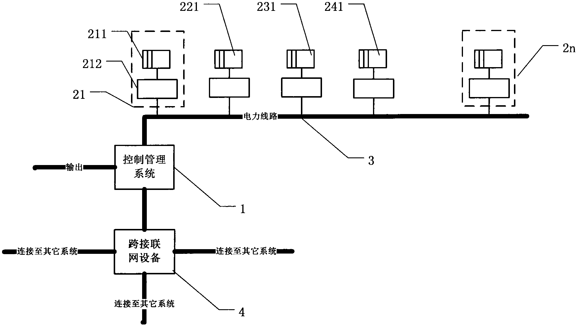
[0019] The present invention designs a distributed power station system, such as figure 1 The schematic diagram of the topological principle structure is shown. The system consists of a power line connecting multiple power generation units and control management systems freely distributed in space. However, in practical applications, many such power lines may be interwoven (not shown). From the figure, the system includes various scales and various forms of distributed power generation units distributed everywhere, power lines connecting power generation units, control management systems, and networked equipment that connect across different systems and lines etc.

[0020] As the most basic core ...


PUM


Abstract

The invention discloses a distributed power station system which comprises a remote control management system, a plurality of space freely distributed generating monomers and an electric power circuit which is connected with all generating monomers and used for collecting electric energy into the control management system, wherein the generating monomers are provided with energy bodies and energy body controllers one to one, the energy body controllers are connected between the electric power circuit and the output ends of the energy bodies, facing to the electric power circuit; and the energy bodies are energy collecting and converting equipment of one type of wind power, air power, photovoltaic, methane, geotherm, waterpower power generation, electrothermic and the like. Through energy transmission of the energy body controllers and the electric power circuit, the new energy popularization is especially suitable for implementation and deployment in a developed area, can greatly reduce energy system loss, reduce transmission line investment and line loss, achieves high utilization rate and increases the redundancy rate of the system. Through implementation of the invention, the application and popularization speeds of new energies are greatly increased.

Description

technical field [0001] The invention relates to a new pattern of energy utilization, in particular to the field of planning and structure of a power station that adopts various forms to generate electric energy and occupies flexible space and land. Background technique [0002] With the increasing scarcity of earth resources, the investment cost of basic energy is rising day by day, and various hidden dangers of safety and pollution are ubiquitous. Wind energy, solar energy, hydropower and other renewable "Safe, environmentally friendly energy is getting more and more attention. However, at present, renewable energy including wind energy and solar energy is basically limited to the application of large-scale power stations. However, since the geographical distribution of these energy resources is usually far away from places with relatively developed energy demand; even if the distance is relatively close, the construction of large-scale power stations requires Occupying a ...

Claims


Application Information

Patent Timeline
Patent Type & Authority Applications(China)
IPC IPC(8): H02J1/00H02J13/00
CPCH02J3/382Y04S20/18H02J3/386Y02E10/763H02J3/383H02J1/00H02J13/0075H02J13/00Y02E10/563H02J13/0006Y02B90/228H02J3/381H02J3/04H02J13/0024Y04S10/123Y04S10/30Y04S40/126H02J13/00009H02J2300/40H02J13/00002H02J2300/28H02J2300/20H02J2300/24H02J13/00024Y02E10/56Y02E10/76Y02E40/70Y02E60/00Y04S10/50Y04S40/121H02J3/46H02J13/00022Y04S10/12
Inventor 瞿磊
Owner SUZHOU DONGLING VIBRATION TEST INSTR
Why Eureka
Try Eureka