
Device and method for manufacturing optical fiber prefabrication rod mandrel

A technology of optical fiber prefabricated rods and core rods, which is applied to the device for manufacturing optical fiber prefabricated rods and core rods, and in the field of manufacturing optical fiber prefabricated rods. Fluctuation of growth rate and density, reduction of uneven temperature distribution, uniform growth effect

Active Publication Date: 2013-01-09
ZHONGTIAN TECH ADVANCED MATERIALS CO LTD +2
View PDF3 Cites 0 Cited by
  • Summary
  • Abstract
  • Description
  • Claims
  • Application Information

AI Technical Summary

Problems solved by technology

[0005] Chinese invention patents ZL02137584.4 and 03114747.X respectively introduced the method of using disc or cylindrical airflow regulators to eliminate the airflow disturbance in the reaction vessel, but did not propose a method for stabilizing the negative pressure in the chamber
[0006] Chinese invention patent 200910096092.7 controls the flow rate of supplementary air through the automatic pressure regulating device connected to the exhaust pipe, so as to achieve the purpose of stabilizing the internal pressure of the reaction vessel, but only controlling the supplementary air at the exhaust port cannot ensure that the spherical reaction chamber is included and the stability of the airflow in the entire space of the upper chamber

Method used


Image

  • Device and method for manufacturing optical fiber prefabrication rod mandrel
  • Device and method for manufacturing optical fiber prefabrication rod mandrel
  • Device and method for manufacturing optical fiber prefabrication rod mandrel

Examples


Embodiment 1

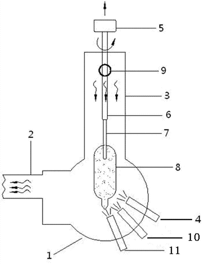
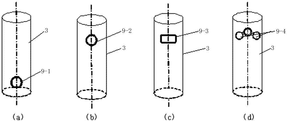
[0043] Embodiment one: figure 2 (a) is the first setting method of the supplementary air outlet, and a circular supplementary air outlet with a diameter of 100mm is installed at a position 200mm away from the lower end of the upper cavity. A quartz target rod 7 is installed on the boom 6, and the target rod 7 is lowered to a suitable position in the spherical reaction chamber 1 to be opposite to the torch. Open the exhaust device and start exhausting, start to pass into hydrogen and oxygen in the blowtorch simultaneously and ignite to produce hydrogen-oxygen flame, then pass into SiCl to the 3rd blowtorch 11 4 and GeCl 4 Gas raw material, which undergoes hydrolysis reaction in an oxyhydrogen flame to form SiO 2 、GeO 2 The powder is deposited on the lower end of the target rod to form the core layer of the prefabricated mandrel, and at the same time, SiCl is injected into the first torch 4 and the second torch 10 respectively. 4 Gas feedstock, resulting in SiO 2 The powde...

Embodiment 2

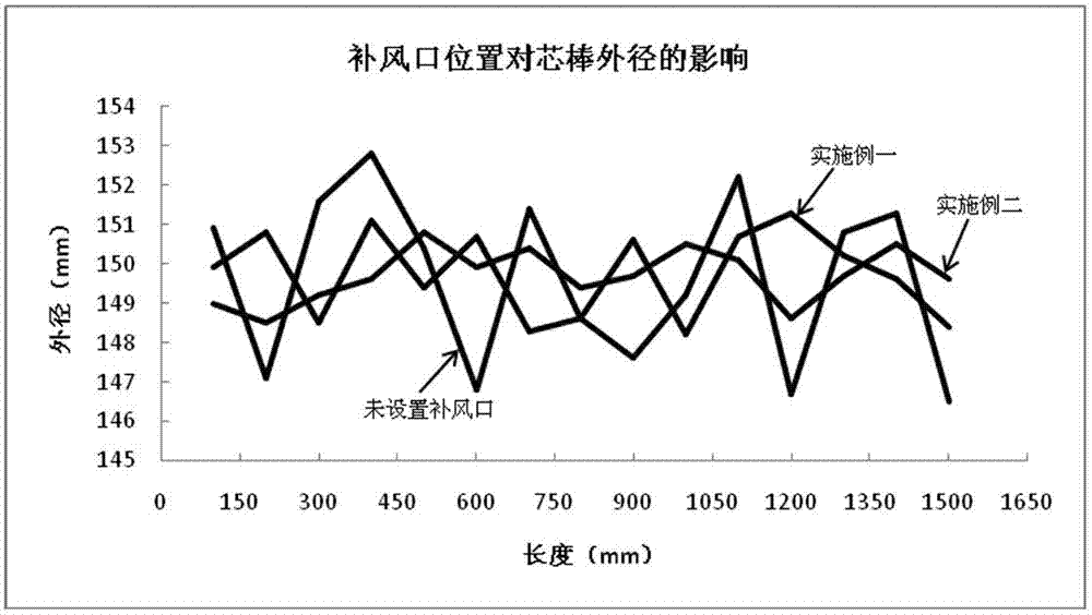
[0044] Embodiment two: figure 2 (b) For the second setting method of the air supply port, a circular air supply port with a diameter of 100mm is set at a position 200mm from the upper end of the upper cavity. After the air supply port is set at the upper position, the internal pressure and air flow of the entire space including the upper cavity can be stabilized. At the end of the deposition, the outer diameter and core-to-cover ratio of the preform are measured. From image 3 It can be seen from the figure that when the air supply port is set at this position, the fluctuation range of the outer diameter of the preform along the length direction is ±1.5mm, and the fluctuation is small. From Figure 5 It can be seen that the core-to-package ratio of the preform varies along the length direction, and the core-to-package ratio fluctuates from 3.62 to 3.66. same image 3 and Figure 5 Compared with the case where no supplementary air port is set in the case, the quality of ...

Embodiment 3

[0045] Embodiment three: figure 2 (c) For the third setting method of the air supply port, a rectangular air supply port with a length of 100mm and a width of 80mm is set at a position 200mm away from the upper end of the upper cavity. At the end of the deposition, the outer diameter and core-to-cover ratio of the preform are measured. From Figure 4 It can be seen from the figure that when the air supply port of this shape is set at this position, the fluctuation range of the outer diameter of the preform along the length direction is ±2mm. From Figure 6 It can be seen that the core-to-package ratio of the preform varies along the length direction, and the core-to-package ratio fluctuates from 3.55 to 3.72.


PUM

PropertyMeasurementUnit
heightaaaaaaaaaa
diameteraaaaaaaaaa

Abstract

The invention discloses a device and a method for manufacturing an optical fiber prefabrication rod mandrel and relates to manufacturing of the optical fiber prefabrication rod mandrel, in particular to the device and the method for manufacturing the optical fiber prefabrication rod mandrel through axial vapor deposition (VAD). The mandrel manufactured by the method can grow more uniformly along the axial direction and the core bag ratio fluctuates slightly. The device comprises a spherical reaction cavity, an exhaust pipeline, an upper cavity, a first blow lamp, a second blow lamp and a third blow lamp, a revolving shaft 5 and a suspension rod; and the upper cavity is provided with an air supplement port. During the preparation of a powder mandrel, a quartz glass target rod is arranged on the suspension rod, and then the suspension rod is placed in the reaction cavity, and hydrogen and oxygen are introduced into the blow lamp and then are ignited in the reaction cavity to produce oxyhydrogen flame. Then the raw material air, such as SiCl4, GeCl4 and the like is fed into the oxyhydrogen flame through the blow lamp, and is subjected to hydrolysis reaction; and SiO2, and GeO2 powdergenerated through oxidation is deposited at the lower end of the target rod due to thermophoresis movement. Simultaneously, the target rod is rotated and is lifted upward to ensure that the powder isdeposited at the lower end of the target rod to form a cylindrical powder mandrel with a core layer and an optical cladding.

Description

technical field [0001] The invention relates to a device and method for manufacturing an optical fiber prefabricated core rod, which relates to the manufacture of an optical fiber preformed rod, specifically a device and method for manufacturing an optical fiber preformed rod by axial vapor deposition (VAD) . The mandrel manufactured by this method grows more uniformly along the axial direction, and the core-to-package ratio fluctuates less. Background technique [0002] With the development of optical fiber preform technology, a two-step method is currently used to manufacture optical fiber preforms, that is, the core rod (including the core layer and optical cladding) is manufactured first, and then the cladding or sleeve is deposited outside the core rod. An optical fiber preform is produced. The manufacturing methods of optical fiber preform core rod mainly include axial vapor deposition (VAD), modified chemical vapor deposition (MCVD), plasma chemical vapor deposition...

Claims


Application Information

Patent Timeline
Patent Type & Authority Patents(China)
IPC IPC(8): C03B37/018
CPCC03B37/01486C03B37/01406C03B37/0144
Inventor 薛济萍李璇钱宜刚谢康沈一春庄卫星薛驰
Owner ZHONGTIAN TECH ADVANCED MATERIALS CO LTD
Learn More