Antenna for reducing radar scattering cross section

A radar cross-section and antenna technology, applied in antenna coupling, antenna grounding device, radiation element structure, etc., can solve the problems of high technical content of structural RAM, increased volume, weight and cost, and unstable shrinkage performance. Achieve the effects of weakening mutual coupling strength, simple structure, and easy processing

Inactive Publication Date: 2011-09-07
XIDIAN UNIV
View PDF1 Cites 33 Cited by
  • Summary
  • Abstract
  • Description
  • Claims
  • Application Information

AI Technical Summary

Problems solved by technology

However, stealth is completely lost when the radar is turned on
[0005] (2) Airspace Stealth
However, electro-absorbing materials tend to be large in size, while magnetic-absorbing materials will increase the weight of the antenna to a large extent, and the technical content of structural RAM is high, which will greatly increase the design cost
For the stealth of out-of-band radar, there are many researches at present, such as using a structural RAM called Frequency Selective Surface (FSS) to make a radome, which transmits the microwave energy radiation in the frequency band and reflects the out-of-band power obliquely , so as to achieve the purpose of reducing the RCS outside the antenna band, but this kind of method often needs to design a complex conformal radome according to the actual shape, and leave a certain distance between the antenna and the radome, so the volume, weight and cost increase , often contradicts the design requirements, and the reduction performance will be affected by installation errors and become unstable. It is powerless to threat radar waves of the same frequency band and polarization, making it necessary to achieve stealth for threat radar waves of the same polarization within the antenna working frequency band. extremely difficult

Method used


Image

  • Antenna for reducing radar scattering cross section
  • Antenna for reducing radar scattering cross section
  • Antenna for reducing radar scattering cross section

Examples


Embodiment Construction

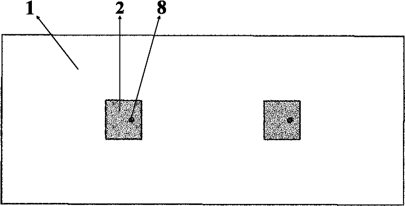
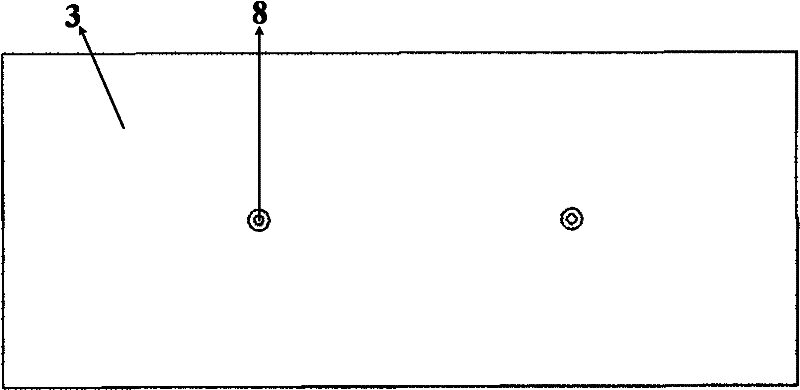
[0029] refer to figure 1 and figure 2 , the existing two microstrip patch antennas working at 8.2GHz are composed of a dielectric board 1, two microstrip radiating units 2 and a grounding board 3. The dielectric board 1 uses double-sided copper clad laminates, and the microstrip radiating unit 2 is located on the dielectric board The ground plate 3 is located on the lower surface of the dielectric plate, the flange plate of the SMA head is welded on the ground plate 3, and each microstrip radiation unit 2 has a via hole 8 penetrating the dielectric plate 1, and the inner core of the SMA head Weld the via hole on the microstrip radiating unit to feed the antenna.

[0030] The invention is right figure 1 and figure 2 The antenna shown is modified in that a high-impedance surface structure is used to reduce its radar cross-section.

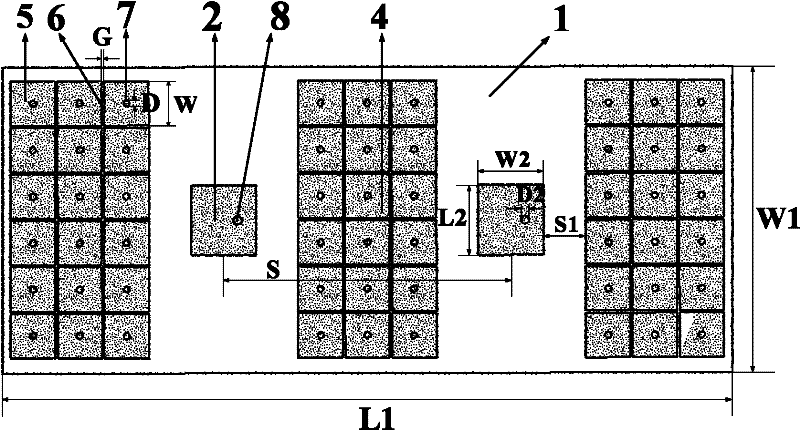
[0031] refer to image 3 and Figure 4 , the present invention comprises: a dielectric board 1, two microstrip radiation units 2, a groundin...


PUM


Abstract

The invention discloses an antenna for reducing a radar scattering cross section, aiming to solve the problem of large radar scattering cross section of the traditional microstrip antenna. The antenna comprises a dielectric slab (1), a microstrip radiating unit (2) and an earth plate (3), wherein the microstrip radiating unit is arranged at the upper surface of the dielectric slab, and the earth plate is arranged at the lower surface of the dielectric slab; both sides of the microstrip radiating unit are provided with a high impedance surface array (4) respectively; each high impedance surface array is formed by arranging a plurality of metal chips into a rectangle, a gap is arranged between the adjacent metal chips to form a capacitor C; the center of each metal chip is provided with a metal via hole which penetrates through the dielectric slab; a current path connected by the via holes can form an inductor L, and the capacitor and the inductor form an LC resonant circuit; the frequency of the resonant circuit can be adjusted to be coincident with the working frequency of the antenna, thus realizing scattered field compensation of the high impedance surface array and the antenna. The invention has stable performance of reducing radar scattering cross section within and outside the frequency band of the antenna, and also has no effect on the size, weight and cost of the antenna.

Description

technical field [0001] The invention belongs to the technical field of antennas, and relates to a high-impedance surface, in particular to an antenna which utilizes the high-impedance surface to reduce the radar scattering cross section, and is used for realizing the stealth of the antenna. Background technique [0002] The confrontation between stealth and anti-stealth technology is an important aspect of radar detection technology. Stealth technology is a general term for various technologies that study how to reduce the ability of targets to be discovered by detection systems such as electromagnetic waves, sound waves, infrared light, and visible light. Radar stealth technology is the focus. The radar cross-section RCS is a measure of the return scattering power of a target in a given direction under the illumination of a plane wave, and is an important parameter that characterizes the identifiable characteristics of a target in radar detection technology, stealth and ant...

Claims


Application Information

Patent Timeline
Patent Type & Authority Applications(China)
IPC IPC(8): H01Q1/38H01Q1/48H01Q1/52
Inventor 张鹏飞张帅龚琦路宝龚书喜关莹姜文王文涛赵晋娟
Owner XIDIAN UNIV
Why Eureka
Try Eureka