

Optically isotropic liquid crystal medium and optical element
A technology of optical isotropy and liquid crystal phase, applied in liquid crystal materials, optics, nonlinear optics, etc., can solve the problem of high voltage
- Summary
- Abstract
- Description
- Claims
- Application Information
AI Technical Summary
Problems solved by technology
Method used
Image

Examples
preparation example Construction
[0240] The liquid crystal composition of the present invention can generally be prepared by known methods, for example, a method of dissolving desired components at high temperature.
[0241] 4 Composition of liquid crystal phase with optical isotropy
[0242] 4.1 Composition of liquid crystal phase with optical isotropy
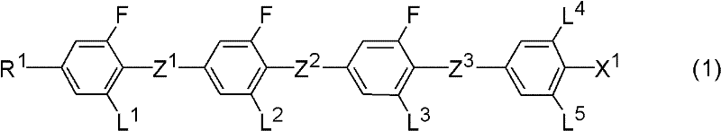
[0243] A fourth aspect of the present invention is a composition containing a compound represented by formula (1) and a chiral agent, which is a liquid crystal composition usable in an optical device driven by an optically isotropic liquid crystal phase. The liquid crystal composition is a composition showing a liquid crystal phase with optical isotropy.
[0244] Although the compound represented by formula (1) is a tetracyclic compound, it has a low clearing point, and has a large dielectric anisotropy and a large refractive index anisotropy. Therefore, in order to show excellent characteristics, The content of the compound represented by formula (1) ...
example
[0349] Since the obtained compounds were obtained by 1 The nuclear magnetic resonance spectrum obtained by H-NMR analysis, the gas chromatogram (gas chromatogram) obtained by gas chromatography (Gas Chromatography, GC) analysis, etc. are used for identification, so the analysis method will be explained first.
[0350] 1 H-NMR analysis: DRX-500 (manufactured by Bruker BioSpin Co., Ltd.) was used as a measurement device. The measurement was carried out by dissolving the sample prepared in the example etc. in CDCl 3 etc. in a deuterated solvent in which the sample can be dissolved, and carried out at room temperature at 500 MHz with 24 accumulation times. In addition, in the description of the obtained nuclear magnetic resonance spectrum, s indicates a singlet (singlet), d indicates a doublet (doublet), t indicates a triplet (triplet), q indicates a quartet (quartet), m indicates a multiplet (multiplet). Also, Tetramethylsilane (TMS) was used as a standard substance for the z...
Synthetic example 1
[0379] Synthesis of formula (S1-8)
[0380]
[0381] The synthesis process is shown in the figure below.
[0382]
[0383] Synthesis of compound (S1-2)
[0384] 88.3g of (S1-1) and 7.54g of catalyst, 900ml of tetrahydrofuran (Tetrahydrofuran, THF) were loaded into the reactor under nitrogen atmosphere, and 2mol / L of butylmagnesium chloride (butylmagnesium chloride) was added dropwise therein at room temperature chloride) in THF and refluxed for 4 hours. The reaction liquid was cooled to room temperature, toluene was added there, and this was washed with 1N-hydrochloric acid and water. After drying with magnesium sulfate, the solvent was distilled off under reduced pressure. Purified by silica gel column chromatography using heptane as a developing solvent, and dried under reduced pressure to obtain 75.7 g of (S1-2). The yield of (S1-2) from (S1-1) was 93.1%.
[0385] Synthesis of compound (S1-3)
[0386] Put 55.5g (S1-2) and 550ml tetrahydro...
PUM
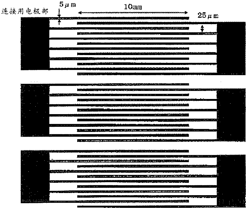
| Property | Measurement | Unit |
|---|---|---|
| Film thickness | aaaaa | aaaaa |
| Interval | aaaaa | aaaaa |
Abstract
Description
Claims
Application Information