Path planning method for complicated-shape workpiece of robot bead weld based on radial bias

A trajectory planning and robot technology, applied in the direction of manufacturing tools, welding equipment, arc welding equipment, etc., can solve the problems of reducing production efficiency, affecting the quality of surfacing welding, increasing labor hours, etc., to achieve improved use efficiency, broad application prospects, good The effect of the surfacing effect

Inactive Publication Date: 2011-10-19
SOUTHEAST UNIV
View PDF3 Cites 27 Cited by
  • Summary
  • Abstract
  • Description
  • Claims
  • Application Information

AI Technical Summary

Problems solved by technology

In this way, too much solder in the blind area needs to be polished, or too little solder in the blind area needs to

Method used


Image

  • Path planning method for complicated-shape workpiece of robot bead weld based on radial bias
  • Path planning method for complicated-shape workpiece of robot bead weld based on radial bias
  • Path planning method for complicated-shape workpiece of robot bead weld based on radial bias

Examples


Embodiment Construction

[0029] The invention will be further described in conjunction with the accompanying drawings.

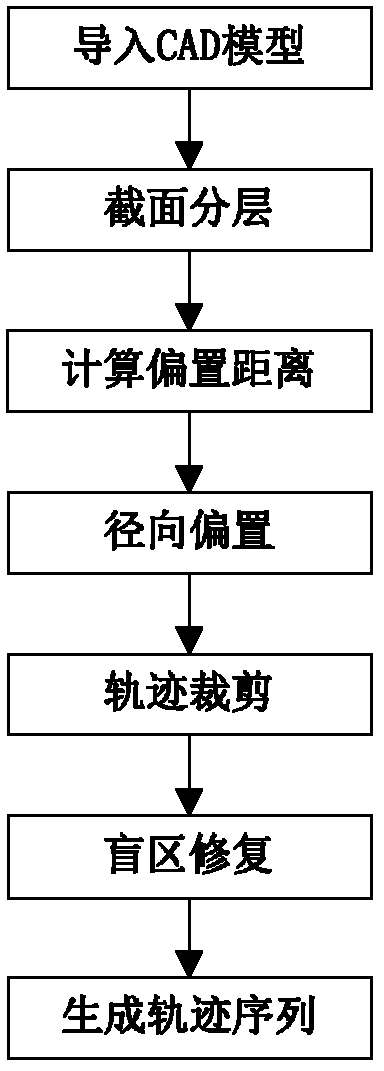
[0030] The main process of this method is as referenced figure 1 As shown, it mainly includes the following steps:

[0031] (1) Import the CAD graphics file of the workpiece;

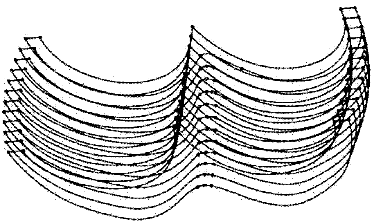
[0032] (2) Perform cross-section layering on the 3D CAD graphics of the workpiece, obtain the cross-section contour line, and generate a cross-section sketch containing the contour line, such as image 3 shown;

[0033] (3) On each section, according to the width of the weld bead and the boundary line of the workpiece ( Figure 4 The lengths of the line segments A1 to M and A2 to N are the boundary lines) to automatically calculate the radial offset distance: first divide the length of the left boundary line by the default weld bead width, and determine the offset distance by rounding up. The offset distance is The width of the weld bead is realized by automatically adjusting the welding parameters (weldi...


PUM


Abstract

The invention relates to a path planning method for a complicated-shape workpiece of robot bead weld based on radial bias. In the method, a robot welding path is automatically planned based on a workpiece computer assisted drafting (CAD) model, contour lines on one side of the cross section of the workpiece are adopted as bias lines, contour lines on another side of the cross section are subjected to radial deflection successively, welding path lines of the cross section are automatically generated to ensure the appearance precision of the workpiece and distance between the path lines and solve the problems of self-cross of rings, straight line segment disappearance and the like. For the bias lines with excessively-changed curvature, subsection bias is performed according to curvature characteristics to adapt to complicated profile, a repair arithmetic is designed according to the requirement of a welding process and appearance characteristics of a workpiece model, the deflected path lines are adjusted to repair a dead area, and the workloads required by repairing welding and polishing are reduced. Due to the adoption of different appearances such as the complicated-shape workpiece of an arc welding robot in the method, the programming time of robot welding operation can be greatly shortened, and the service efficiency of the robot is obviously improved.

Description

technical field [0001] The present invention relates to a trajectory planning method for robot surfacing workpieces with complex shapes based on radial offset. The method can automatically plan robot welding paths based on workpiece CAD models, and is suitable for using arc welding robots to surfacing with different shapes including complex shapes. In the case of externally shaped workpieces, it belongs to the fields of welding automation and machine manufacturing. Background technique [0002] Surfacing welding is a welding method in which metal is melted by electric welding or gas welding and stacked on the base of tools or machine parts to manufacture workpieces. In particular, some complex shape workpieces have limitations when using casting or forging, and surfacing welding must be used. Since the workpiece formed by surfacing welding has the advantages of high bonding strength, small residual stress, short cycle and high efficiency, especially with the promotion and p...

Claims


Application Information

Patent Timeline
IPC IPC(8): B23K9/04
Inventor 孟正大程学刚桂文斌周源王成
Owner SOUTHEAST UNIV
Why Eureka
Try Eureka