Optical laminated body, polarizer, display device and manufacturing method of optical laminated body

A technology of optical laminates and optical functional layers, applied in chemical instruments and methods, optics, optical components, etc., can solve the problems of reduced contrast, whitening of images displayed in black, etc., and achieves the effect of excellent manufacturing stability

Active Publication Date: 2011-10-19
TOMOEGAWA PAPER CO LTD
View PDF9 Cites 12 Cited by
  • Summary
  • Abstract
  • Description
  • Claims
  • Application Information

AI Technical Summary

Problems solved by technology

[0004] When an optical laminate is used on the outermost surface of a display, when used in a bright room, there is ...

Method used


Image

  • Optical laminated body, polarizer, display device and manufacturing method of optical laminated body
  • Optical laminated body, polarizer, display device and manufacturing method of optical laminated body
  • Optical laminated body, polarizer, display device and manufacturing method of optical laminated body

Examples


manufacture example 1

[0163] (manufacture of production example 1 synthetic montmorillonite)

[0164] Add 4L of water to a 10L beaker, and dissolve No. 3 water glass (SiO 2 28%, Na 2 (09%, molar ratio 3.22) 860g, add 95% sulfuric acid 162g in one go and stir, obtain silicate solution. Next, dissolve MgCl in 1 L of water 2 ·6H 2 O primary reagent (purity 98%) 560g, it is added in the aforementioned silicic acid solution to prepare homogeneous mixed solution. This was dropped into 3.6 L of 2N-NaOH solution over 5 minutes and stirred. Immediately filter the obtained reaction precipitate with a cross-flow (Cross flow) filtration system [Cross flow filter (ceramic membrane filter: pore size 2 μm, tubular type, filtration area 400 cm 2 ), pressurization: 2kg / cm 2 , Filter cloth: Tetoron 1310] After filtering and fully washing, add 200ml of water and Li(OH)·H 2 O 14.5 g of the resulting solution was made into a slurry. Move it into the autoclave, at 41kg / cm 2 , 250°C to make it hydrothermally rea...

manufacture example 2

[0165] (Production Example 2 Production of Synthetic Smectite-Based Layered Organoclay A)

[0166]20 g of the synthetic montmorillonite synthesized in Production Example 1 was dispersed in 1000 ml of tap water to form a suspension. Add 500 ml of an aqueous solution of a quaternary ammonium salt (98% containing product) of the following formula (II) that is equivalent to 1.00 times the cation exchange capacity of the synthetic montmorillonite to the aforementioned synthetic montmorillonite suspension, and stir This was allowed to react at room temperature for 2 hours. The resultant is separated into solid and liquid, washed, and dried after removing by-product salts to obtain the synthetic montmorillonite-based layered organoclay A.

[0167]

Embodiment 1

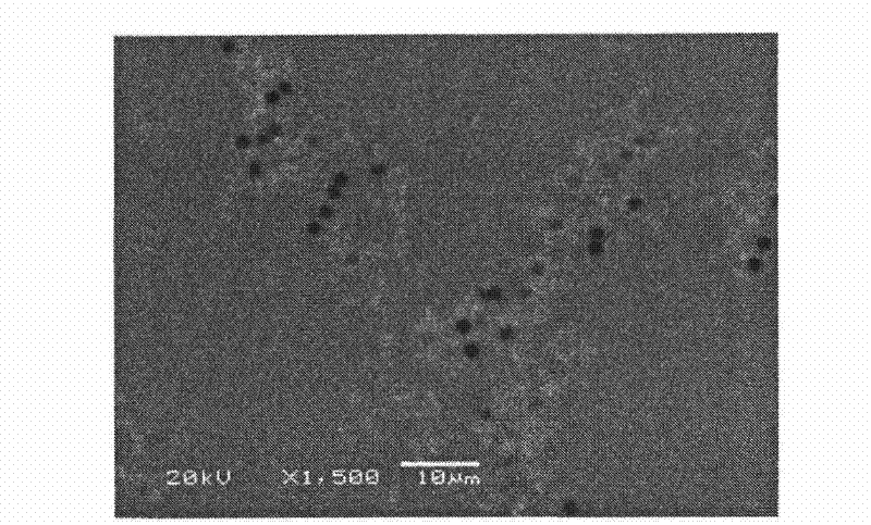
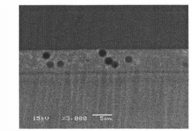
[0169] The prescribed mixture as described in Table 1 containing the aforementioned layered organoclay A was stirred with a disperser for 30 minutes, and the coating material for forming an optical functional layer thus obtained was applied by roll coating (line speed: 20 m / min). On one side of a TAC (manufactured by Fuji Film Co., Ltd.; TD60UL) transparent substrate with a film thickness of 60 μm and a total light transmittance of 92%, pre-dry at 30 to 50°C for 20 seconds, and then dry at 100°C for 1 The coating film was cured by ultraviolet irradiation (lamp: concentrated type high-pressure mercury lamp, lamp output power: 120W / cm, number of lamps: 4, irradiation distance: 20cm) in a nitrogen atmosphere (nitrogen replacement) for 1 minute. Thus, the optical laminated body of Example 1 which has an optical function layer with a thickness of 5.9 micrometers was obtained. Here, the SEM results observed from the optical function layer of the obtained optical laminated body are a...


PUM


Abstract

The invention provides an optical laminated body, a polarizer, a display device and a manufacturing method of the optical laminated body. The invention aims to provide a structural body having dazzle prevention, dark excellence in a bright chamber and capable of achieving high dark chamber contrast, an optical laminated body with excellent manufacturing stability and a manufacturing method of the optical laminated body. Furthermore, the invention aims to provide a polarizer having the optical laminated body and a display device. The optical laminated body provided in the invention is characterized in that an optical functional layer is laminated on a translucent matrix. The optical functional layer comprises a first phase having relatively large amounts of resin components, a second phase having relatively large amounts of inorganic components and particles, wherein, the second phase is concentrated on the periphery of the particles.

Description

technical field [0001] The present invention relates to an optical laminate, a polarizing plate, a display device, and a method for producing an optical laminate characterized in that a second phase is concentrated around fine particles constituting an optical functional layer of the optical laminate. The optical laminated body of the present invention can be provided on the surface of a display such as a liquid crystal display (LCD), a plasma display (PDP), an organic electroluminescent display (OLED), or used as a constituent member of a display. The output efficiency of the light generated in the organic EL layer to the outside of the organic EL is improved, and it can be preferably used on the viewing surface side. In particular, it relates to an optical laminate that emphasizes visibility such as anti-glare properties, black in a bright room, and contrast in a dark room, and the optical laminate can be suitably used, for example, in displays for televisions. Background ...

Claims


Application Information

Patent Timeline
IPC IPC(8): G02B5/02G02B1/11G02B5/30B32B27/06B32B27/18
CPCB29D11/0073B32B27/06B32B27/18B82Y40/00G02B1/11G02B5/3041G02F1/133528
Inventor 森内英辉中西隆之村田力
Owner TOMOEGAWA PAPER CO LTD
Why Eureka
Try Eureka