Zero point self adjustment and calibration method for catalytic gas sensor

A gas sensor, catalytic technology, applied in the direction of material resistance, which can solve the problems of short calibration period and inability to realize real-time self-calibration zero point.

Inactive Publication Date: 2011-11-09
HARBIN ENG UNIV
View PDF5 Cites 7 Cited by
  • Summary
  • Abstract
  • Description
  • Claims
  • Application Information

AI Technical Summary

Problems solved by technology

[0006] The purpose of the present invention is to solve the following problems in traditional catalytic sensors: (1) the calibration period of traditional catalytic sensors is short (2) the output zero point of traditional catalytic sensors can only be adjusted by laboratory calibration, and real-time self-calibration cannot be realized zero point

Method used


Image

  • Zero point self adjustment and calibration method for catalytic gas sensor
  • Zero point self adjustment and calibration method for catalytic gas sensor
  • Zero point self adjustment and calibration method for catalytic gas sensor

Examples


Embodiment Construction

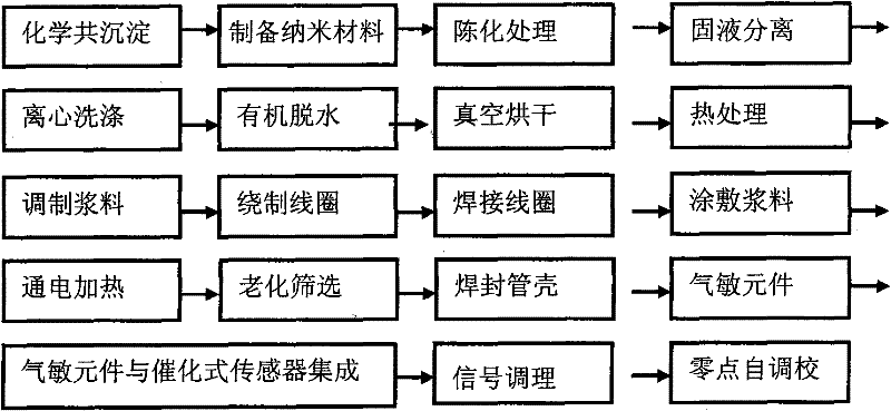
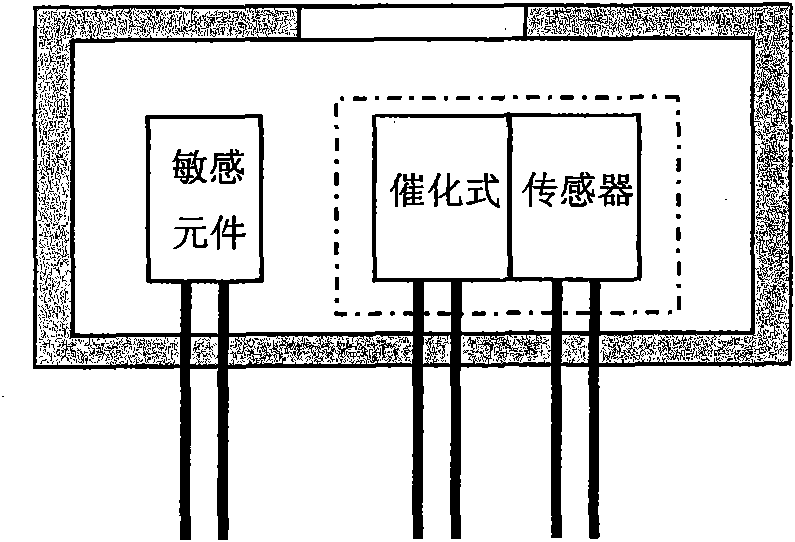
[0023] refer to figure 1 , indicating the process flow chart for the preparation of low-range gas sensor sensors. The process consists of the following process steps: preparation of nanocomposites-aging-solid-liquid separation-washing-dehydration-drying-heat treatment-slurry-coil winding- Welding-coating-heating-tube sealing-integration with catalytic gas sensor-zero point self-adjustment. The manufacturing methods between the various steps can be combined according to specific requirements.

[0024] The specific implementation is as follows:

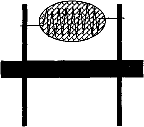
[0025] a. The nano-semiconductor tin dioxide, antimony pentoxide and cerium oxide composite sensitive materials are prepared by chemical co-precipitation method, and the materials are formed after aging, centrifugal solid-liquid separation, deionized washing, organic solvent dehydration, vacuum drying and heat treatment For sensitive materials with lower resistivity, when the sensitive material forms a spherical body with a diameter o...


PUM

PropertyMeasurementUnit
diameteraaaaaaaaaa
electrical resistanceaaaaaaaaaa
diameteraaaaaaaaaa

Abstract

The invention provides a zero point self adjustment and calibration method for a catalytic gas sensor. A nano-semiconductor tin dioxide, antimony pentoxide and cerium oxide composite sensitive material is prepared by a chemical coprecipitation method; the sensitive material is formed by aging, solid-liquid separation by centrifugation, deionizing washing, dehydration by organic solvents, vacuum drying, and heat treatment; and the sensitive material is prepared into slurry by glycerin. By coiling technology, a coil with a diameter of 0.2 mm is coiled by a wire with a diameter of 0.018 mm, and is suspendedly welded on a standard two-feet socket. The sensitive slurry is coated on the coil; the coil is heated by ohmic heating to allow the slurry to be burned into a small ball with certain strength; a shell with holes is sealed on the socket by capacitor discharge welding; and a gas sensitive element with a full scale being less than the volume fraction of 10*10-6v/V for liquefied petroleum gas (natural liquefied gas, hydrogen, organic gas) is produced. The gas sensitive element is integrated with the catalytic gas sensor; with the characteristic that the lowest detection limit of the catalytic gas sensor (a volume fraction of 50*10-6 v/V) is much higher than the full scale of the gas sensitive element, when the detection limit of the gas sensitive element is lower than the full scale, the concentration of ambient detected gas is considered to be nearly zero, and the zero point of the sensor is adjusted by a one-chip microcomputer of a conditioning circuit of the catalytic gas sensor; therefore the function of zero point self adjustment and calibration of the catalytic gas sensor is realized; the invention solves the problem of zero point drift during long-term use of the catalytic gas sensor, realizes the self adjustment and calibration function of the self adjustment and calibration, prolongs the alignment calibration period of the self adjustment and calibration.

Description

(1) Technical field [0001] The invention belongs to the field of sensor manufacturing, in particular to a zero point self-adjustment method of a catalytic gas sensor. (2) Background technology [0002] There are many types and sensitive mechanisms involved in gas sensors. Among them, catalytic gas sensors are the most widely used type of gas sensors due to their linear output, quantitative calibration, and high precision. [0003] The semiconductor principle gas sensor is the most widely used sensor in the combustible gas sensor family. Catalytic gas sensors have the following problems, which affect their performance and applications. (1) The calibration period of traditional catalytic sensors is short. In general, the catalytic gas sensor used in coal mine needs to be calibrated every 7 days, the catalytic gas sensor used in chemical hazardous environment is calibrated every 6 months, and the catalytic gas sensor used in civil places is calibrated every 12 months. Among ...

Claims


Application Information

Patent Timeline
Patent Type & Authority Applications(China)
IPC IPC(8): G01N27/16
Inventor 张洪泉丁喜波张强修德斌刘晓波孙丽美
Owner HARBIN ENG UNIV
Why Eureka
Try Eureka