Method and equipment for manufacturing gradient functional structure

A gradient function and manufacturing method technology, applied in the direction of manufacturing tools, welding equipment, non-electric welding equipment, etc., can solve the problems of short service life, high manufacturing cost, long processing time, etc., to expand the application field and scope, important Engineering application value, effect of improving welding wire deposition rate

Inactive Publication Date: 2013-07-03
CHONGQING UNIV
View PDF5 Cites 3 Cited by
  • Summary
  • Abstract
  • Description
  • Claims
  • Application Information

AI Technical Summary

Problems solved by technology

[0002] How to give full play to the manufacturing advantages of welding technology and the performance of modern structural materials, and quickly manufacture new high-performance special structural parts / parts / components / devices / systems with high torque, low noise, low energy consumption, and pollution-free (such as special drive shafts, piston rod, high-speed and heavy-duty gears, special rotors and blades, special hub shafts, guide rails, gear rollers, rolls, molds, etc.), especially to solve extreme and special circumstances, lightweight, long life, high reliability, high performance new The problems of high energy consumption, high material consumption, long processing cycle and short service life of special components and their systems are key technologies in the field of important equipment in mechanical engineering
[0003] Under extreme service conditions, the high-performance special parts of the key basic parts of machinery are mainly manufactured from a single overall structural part (such as forging parts, casting parts) after machining, and the consumption of raw materials, energy, manpower and other resources is relatively high. Large, long processing time, extremely high equipment requirements, high cost investment, low yield rate, high manufacturing cost

Method used


Image

  • Method and equipment for manufacturing gradient functional structure
  • Method and equipment for manufacturing gradient functional structure
  • Method and equipment for manufacturing gradient functional structure

Examples


specific Embodiment

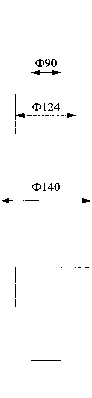
[0040] 1. adopt method of the present invention and equipment manufacture such as image 3 The 42CrMo steel shaft shown is a steel shaft with variable cross-section, the diameter of the small cross-section is 90mm, and the diameter of the large cross-section is 140mm. The material of the shaft is 42CrMo steel. The processing magnetic field strength is 1.0T, the frequency is 25Hz; the ultrasonic frequency is 70KHz, the power is 700W; the welding current is 300A, the wire feeding speed is 30m / min, the shielding gas is pure argon; the welding pool is selected to solidify sequentially along the axial direction A shaft with a large cross-section is grown, and the shaft meets the requirements; the method and equipment can also be used for surfacing repair of similar structural shafts, without obvious surfacing layered structure, and has the characteristics of high performance, low cost and long life.


PUM

PropertyMeasurementUnit
diameteraaaaaaaaaa

Abstract

The invention relates to a method and equipment for manufacturing a gradient functional structure through arc welding and quick forming. By adopting the technology of outer-field compounding, molding, forcible temperature control, sequential growth, and whole welding forming, a double metal gradient material is subjected to in-situ alloying, and the gradient functional structure is manufactured in a near net way; and in the method, an electromagnetic stirring action, an electromagnetic metallurgical action and an ultrasonic welding action are adopted, the large-volume welding pool liquid metal solidification process is comprehensively controlled, and the gradient functional structure is manufactured by matching a high-speed wire feed system, a mould forcible temperature control system, a near net forcible sequential growth whole forming system, and an in-situ alloying gradient material. The equipment is formed by integrating and combining an electromagnetic welding system, an ultrasonic welding system, and an efficient welding system. By the method and the equipment for quickly manufacturing the gradient functional structure by a non-layered welding structure in a low-cost way, a manufacturing period is reduced, production efficiency is improved, and the high reliability and the long service life of the gradient functional structure are guaranteed.

Description

technical field [0001] The invention relates to welding rapid prototyping technology, in particular to a method and equipment for manufacturing a gradient function structure, and belongs to the field of welding technology. Background technique [0002] How to give full play to the manufacturing advantages of welding technology and the performance of modern structural materials, and quickly manufacture new high-performance special structural parts / parts / components / devices / systems with high torque, low noise, low energy consumption, and pollution-free (such as special drive shafts, piston rod, high-speed and heavy-duty gears, special rotors and blades, special hub shafts, guide rails, gear rollers, rolls, molds, etc.), especially to solve extreme and special circumstances, lightweight, long life, high reliability, high performance new The problems of high energy consumption, high material consumption, long processing cycle and short service life of special components and their...

Claims


Application Information

Patent Timeline
Patent Type & Authority Patents(China)
IPC IPC(8): B23K28/02B23K20/10B23K9/16B23K9/32B23K9/08
Inventor 罗键薛克亮项俊锋李飞王小明刘德佳王颖
Owner CHONGQING UNIV
Why Eureka
Try Eureka