
Heat conducting oil smoke residual heat recovery method

A recovery method and flue gas waste heat technology, which is applied in the field of flue gas waste heat utilization, can solve problems such as insufficient utilization of flue gas waste heat, uneconomical pressure in the water heat medium system, and increased loss of effective energy, so as to avoid dew point corrosion. , low pressure resistance requirements and equipment anti-corrosion requirements, and the effect of improving thermal efficiency

Active Publication Date: 2011-11-16
PETROCHINA CO LTD
View PDF12 Cites 14 Cited by
  • Summary
  • Abstract
  • Description
  • Claims
  • Application Information

AI Technical Summary

Problems solved by technology

However, the outlet temperature of the convection chamber of many heating furnaces in oil refineries is usually 280-350 ° C. It is uneconomical to continue to increase the pressure of the water heat medium system, and maintain the water heat medium system at a lower pressure, and the temperature level will decrease accordingly. The loss of effective energy increases, and the waste heat of flue gas cannot be fully utilized

Method used


Image

  • Heat conducting oil smoke residual heat recovery method
  • Heat conducting oil smoke residual heat recovery method
  • Heat conducting oil smoke residual heat recovery method

Examples


Embodiment 1

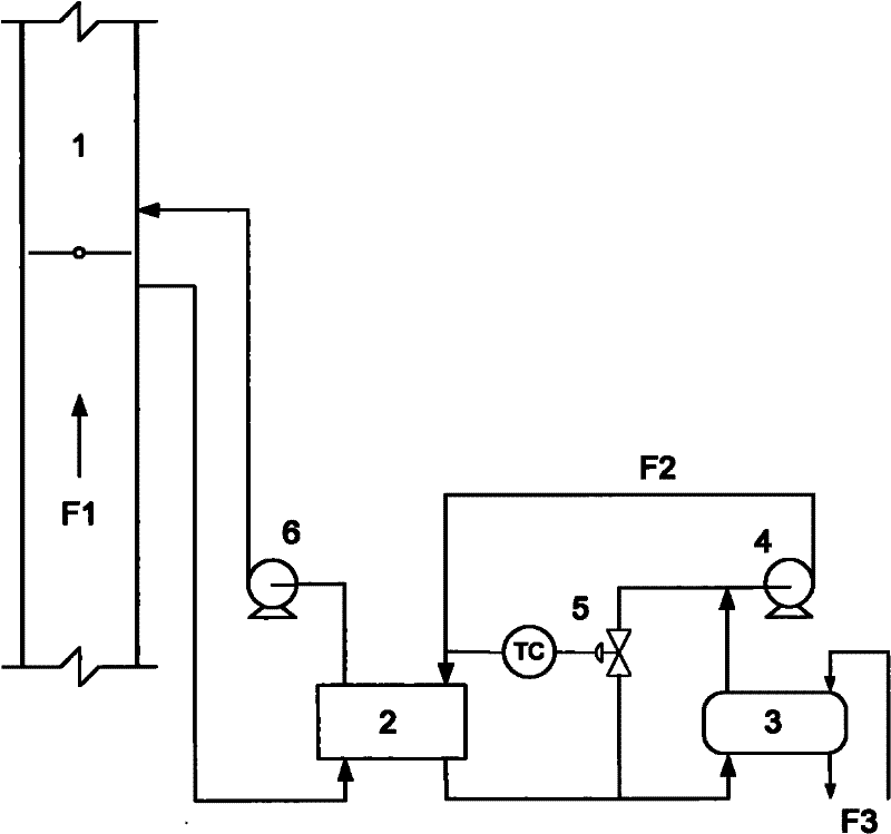
[0035] Process of the present invention see figure 1 . The process is described as follows: use the induced draft fan 6 to guide the flue gas F1 below the inner baffle of the flue 1 to the flue gas-heat transfer oil heat exchanger 2, exchange heat with the heat transfer oil F2, and return it to the upper side of the flue baffle through the induced draft fan to discharge . The flue gas-heat transfer oil heat exchanger 2 is a tubular heat exchanger, the flue gas goes through the shell side, and the heat transfer oil goes through the tube side. The heat transfer oil inlet temperature of the flue gas-heat transfer oil heat exchanger 2 is measured by a thermocouple, and the signal is sent to the bypass flow control valve 5 . The heat transfer oil is divided into two paths from the flue gas-heat transfer oil heat exchanger 2, one of which enters the air preheater 3 to exchange heat with the heating furnace air F3, and after the heat exchange, it is connected to the bypass control...

Embodiment 2

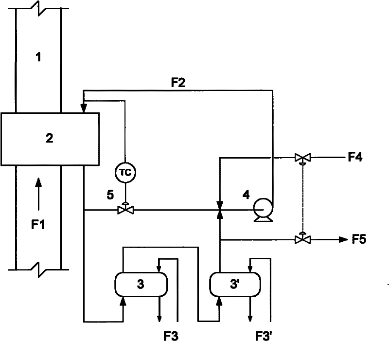
[0038] Process of the present invention see figure 2 . The process is described as follows: the flue gas-heat transfer oil heat exchanger 2 is installed in the flue 1, which is a plate heat exchanger, and the hot flue gas F1 exchanges heat with the heat transfer oil in the flue gas-heat transfer oil heat exchanger 2, and conducts heat The oil is hydrogenated tail oil. After the heat transfer oil passes through the flue gas-heat transfer oil heat exchanger 2, the temperature rises, and the high-temperature heat transfer oil is divided into two strands, and one strand enters the working medium heating area as a heat source, and is used to heat various low-temperature working medium 1F3 and working medium 2F3'. After heating, the temperature decreases and turns into low-temperature heat transfer oil. A part of the low-temperature heat transfer oil leaves the circulation, and the heat transfer oil F5 removed from the cycle enters the next step of the oil treatment process. The h...


PUM


Abstract

The invention relates to a heat conducting oil circulating smoke residual heat recovery method which comprises the following steps of: carrying out heat exchange on high-temperature smoke of a convection chamber outlet of a heating furnace and a stream of heat conducting oil which is lower than the high-temperature smoke at temperature in a smoke-heat conducting oil heat exchanger and dischargingthe smoke with temperature reduction; exchanging heat with a working medium by using one stream of heat conducting oil with temperature rise as a heat source and leading the other stream to pass the side road; combining the heat conducting oil with temperature reduction with the heat conducting oil passing the side road or mixing the led heat conducting oil, the heat conducting oil with temperature reduction after carrying out heat exchange with the working medium and the heat conducting oil in the bypass and returning to the smoke-heat conducting oil heat exchanger to form a heat conducting oil cycle; and monitoring the temperature at a heat conducting oil inlet in the smoke-heat conducting oil heat exchanger and controlling the flow of the heat conducting oil at the bypass through usingtemperature as a parameter so that the temperature of the combined heat conducting oil is higher than the dew point temperature of the smoke. According to the method, dew point corrosion is prevented, great investment is saved, the heat of a smoke residual heat recovery system and other devices can be comprehensively utilized through an open type heat conducting oil cycle and the heat efficiency of the whole device is improved.

Description

technical field [0001] The invention relates to a flue gas waste heat utilization technology, in particular to a heat transfer oil flue gas waste heat recovery method which utilizes heat transfer oil as a heat medium and avoids dew point corrosion. Background technique [0002] The flue gas discharged from the heating furnace carries a large amount of heat, and the exhaust gas loss is the main part of the heat loss of the heating furnace. From the perspective of fuel consumption, every 10°C reduction in exhaust gas temperature can save about 1% of fuel. Therefore, flue gas waste heat recovery is an important means to save energy and improve furnace efficiency. At present, the technologies for reducing the exhaust gas temperature can be divided into two types: direct heat exchange and indirect heat exchange. Direct heat exchange includes introducing the low-temperature medium that needs to be heated into the end of the convection chamber, directly exchanging heat with the fl...

Claims


Application Information

Patent Timeline
Patent Type & Authority Applications(China)
IPC IPC(8): F27D17/00F23L15/00
CPCY02E20/34Y02P10/25
Inventor 白跃华周华群张兆前胡雪生董卫刚陈超李玮
Owner PETROCHINA CO LTD
Learn More