Dye sensitized solar cell with metal line layer and electrodes thereof

A solar cell and dye-sensitized technology, which is applied in the field of metal wire layers of electrodes, can solve problems such as unsatisfactory, time-consuming and labor-intensive, and limit the use of dye-sensitized solar cells, and achieve the effect of reducing the impedance value

Inactive Publication Date: 2011-11-16
JINEX CORP
View PDF3 Cites 8 Cited by
  • Summary
  • Abstract
  • Description
  • Claims
  • Application Information

AI Technical Summary

Problems solved by technology

However, the process of forming the protective film is too time-consuming and labor-intensive, has a very high failure rate, and is not suitable for the production of flexible solar cells, because the structure of the protective film will be destroyed under the flexing action, making the The silver wire is in contact with the electrolyte
What's more, due to the additional protective film, the area of ​​the overall protective film / silver wire covers the surface area of ​​the conductive substrate to a considerable extent, which affects the light transmittance of the electrode
[0008] To sum up, the traditional method to reduce the impedance value of the conductive substrate is not only too time-consuming, but also limits the application of dye-sensitized solar cells, which is not ideal

Method used


Image

  • Dye sensitized solar cell with metal line layer and electrodes thereof
  • Dye sensitized solar cell with metal line layer and electrodes thereof
  • Dye sensitized solar cell with metal line layer and electrodes thereof

Examples


Embodiment 1

[0042] Embodiment 1: Preparation of a working electrode with a metal wire layer of the present invention

[0043] [preparation]

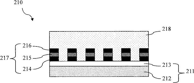
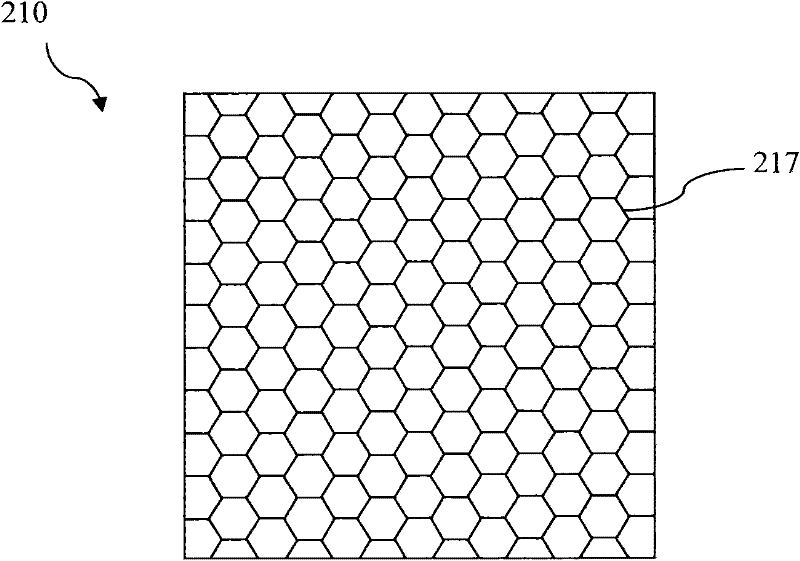
[0044] see Figure 2A , choose glass as the substrate 212 of the conductive substrate 211 of the working electrode (anode) 210 in this embodiment, and fluorine-doped tin oxide (FTO, Fluorine-Doped Oxide) is deposited on the substrate by chemical vapor deposition (CVD) A conductive layer 213 is formed on the surface. implanting nickel metal on the aforementioned conductive layer 213 by vapor deposition to form the first nickel wire layer 214, and then implanting aluminum metal on the aforementioned first nickel wire layer 214 by vapor deposition, An aluminum wire layer 215 is formed, and finally nickel metal is implanted on the aluminum wire layer 215 by evaporation to form a second nickel wire layer 216 . The aforementioned first nickel wire layer 214, aluminum wire layer 215 and second nickel wire layer 216 together constitute the metal wire lay...

Embodiment 2

[0051] Embodiment 2: Preparation of the counter electrode with the metal wire layer of the present invention

[0052] see Figure 3A Select flexible polyethylene naphthalate (PEN) as the substrate 312 of the conductive substrate 311 of the working electrode (anode) 310 in this embodiment, and indium tin oxide (ITO, Indium Tin Oxide) A conductive layer 313 is formed on the surface of the substrate by sputtering. Then titanium metal is implanted on the aforementioned conductive layer 313 by evaporation to form the metal line layer 314 of this embodiment. The shape of the aforementioned metal line layer 314 is as follows Figure 3B As shown, they are parallel lines to maintain good light transmittance of the counter electrode (cathode) 310 .

[0053] Then, a platinum layer is covered on the surface of the conductive layer 313 provided with the metal wire layer 314 by vacuum coating as a catalyst layer 315 (thickness is 1 nm), and the counter electrode (cathode) 310 of this emb...

Embodiment 3

[0054] Embodiment 3: Preparation of the electrochemical device of the present invention

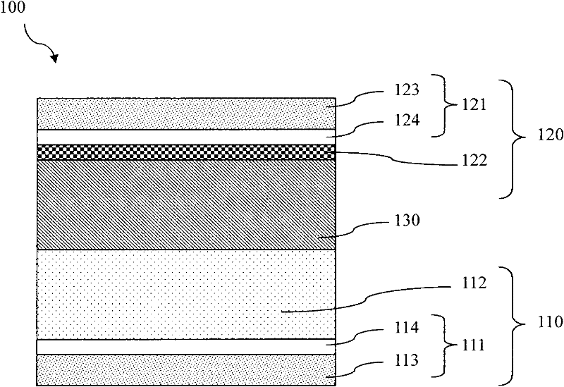
[0055] see Figure 4 , taking the dye-sensitized solar cell 400 as an example of the electrochemical device of this embodiment, the structure of each layer is described as follows:

[0056] A flexible titanium plate (Ti) is selected as the conductive substrate 411 of the working electrode (anode) 410 of this embodiment, and then titanium dioxide nanoparticles (TiO 2 ) coated on it to make TiO with a thickness of about 15 μm 2 / Ti electrode. Then the aforementioned TiO 2 After the / Ti photoelectrode was cut into an area of ​​8 cm x 8 cm (length x width), it was placed in an electric furnace and sintered at 500 ° C for 30 minutes to strengthen the connection force between titanium dioxide nanoparticles. Then at room temperature, the TiO 2 / Ti photoelectrode soaked in 0.3mmol / L photoexcitable dye solution (dissolve 0.036 g of N719 dye in 100 ml of tert-butanol and acetonitrile mixture, ...


PUM

PropertyMeasurementUnit
thicknessaaaaaaaaaa
thicknessaaaaaaaaaa
thicknessaaaaaaaaaa

Abstract

The invention relates to a dye sensitized solar cell with a metal line layer and electrodes thereof. Each electrode of the dye sensitized solar cell comprises a conducting base plate and a metal line layer; the metal line layer can be made of nickel, aluminum, titanium or the combination of nickel, aluminum and titanium which can not react with electrolyte of the dye sensitized solar cell, thus a protection layer is not required to be added to the surface of a metal line. The invention also relates to the dye sensitized solar cell comprising the electrodes. The solar cell comprises a working electrode, a counter electrode, an electrolyte, a metal line layer and a package material, wherein the working electrode comprises a conducting base plate and a photosensitive layer; the counter electrode comprises an conducting base plate and a catalyst layer; the electrolyte is arranged between the working electrode and the counter electrode; the metal line layer is made of nickel, aluminum, titanium or the combination of nickel, aluminum and titanium; and the package material is used for wrapping the electrolyte.

Description

technical field [0001] The present invention relates to a metal wire layer for an electrode of an electrochemical device, especially a metal wire layer for an electrode of a dye-sensitized solar cell. Background technique [0002] Under the dual problems of energy depletion and environmental protection, solar energy is a green energy with great potential. Due to the high cost of silicon solar cells, the technical development of dye-sensitized solar cells (DSSC) with low-cost power generation components has gradually attracted attention. [0003] see figure 1 , the main internal structure of the dye-sensitized solar cell 100 includes a working electrode (anode) 110 , a counter electrode (cathode) 120 , and an electrolyte 130 . The anode 110 includes a conductive substrate 111 and a photosensitive layer 112 for receiving sunlight energy, while the cathode 120 includes a conductive substrate 121 and a catalyst layer 122 with a proper thickness. The aforementioned conductive ...

Claims


Application Information

Patent Timeline
Patent Type & Authority Applications(China)
IPC IPC(8): H01G9/04H01G9/20H01M14/00H01L51/44H01L51/42
CPCY02E10/542Y02E10/549Y02E10/50
Inventor 陈建清谢坤龙
Owner JINEX CORP
Why Eureka
Try Eureka