Tin-lead welding strip for solar photovoltaic assembly and manufacturing method thereof

A solar photovoltaic and manufacturing method technology, applied in photovoltaic power generation, final product manufacturing, sustainable manufacturing/processing, etc., to achieve the effects of low volume resistivity, low melting point, and enhanced adhesion

Inactive Publication Date: 2011-11-23
SHANGHAI WELNEW MICRO ELECTRONICS
View PDF10 Cites 30 Cited by
  • Summary
  • Abstract
  • Description
  • Claims
  • Application Information

AI Technical Summary

Problems solved by technology

However, in the prior art, the method of using hot-dip tin process to cover the tin sol

Method used


Image

  • Tin-lead welding strip for solar photovoltaic assembly and manufacturing method thereof
  • Tin-lead welding strip for solar photovoltaic assembly and manufacturing method thereof
  • Tin-lead welding strip for solar photovoltaic assembly and manufacturing method thereof

Examples


Embodiment 1

[0034] The copper strip substrate is commercially available red copper strip, and the copper strip substrate is subjected to heat treatment at 400° C. for 90 minutes.

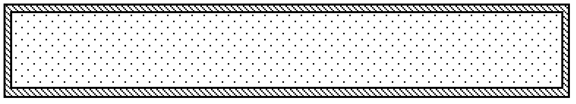
[0035] The heat-treated red copper strip is electroplated through an electroplating solution containing Sn and Pb, and the molar concentration ratio of Sn and Pb is controlled at 30:10; the moving speed of the copper strip substrate is controlled at 10m / min, and the pH value of the electroplating solution is controlled at 1. The temperature of the plating solution is controlled at 20°C, and the current density is controlled at 30A / dm 2 , the electroplating time is controlled at 2 minutes, and the coating thickness is controlled at 10 microns. A solder strip with a weight percentage of tin and lead in the plating layer of 63:37 was obtained.

Embodiment 2

[0037] The copper strip substrate is commercially available red copper strip, and the copper strip substrate is subjected to heat treatment at 750° C. for 30 minutes.

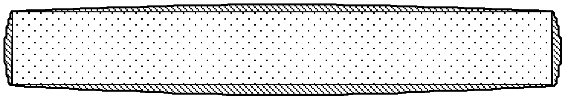
[0038] The heat-treated oxygen-free copper strip is electroplated through an electroplating solution containing Sn and Pb, and the molar concentration ratio of Sn and Pb is controlled at 30:20; the moving speed of the copper strip substrate is controlled at 15m / min, and the pH value of the electroplating solution is controlled at 2. The temperature of the electroplating solution is controlled at 25°C, and the current density is controlled at 40A / dm 2 , the electroplating time is controlled at 1 minute, and the coating thickness is controlled at 15 microns. A solder strip with a weight percentage of tin and lead in the plating layer of 60:40 was obtained.

Embodiment 3

[0040] A commercially available oxygen-free copper strip was used as the base material of the copper strip, and heat treatment was performed on the base material of the copper strip, and the heat treatment was performed at 550° C. for 60 minutes.

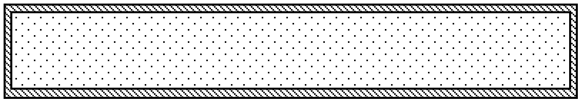
[0041] The heat-treated oxygen-free copper strip is electroplated through an electroplating solution containing Sn and Pb, and the molar concentration ratio of Sn and Pb is controlled at 30:8; the moving speed of the copper strip substrate is controlled at 20m / min, and the pH value of the electroplating solution is controlled at 1.5, the temperature of the electroplating solution is controlled at 15°C, and the current density is controlled at 30A / dm 2 , the electroplating time is controlled at 2 minutes, and the coating thickness is controlled at 8 microns. A solder strip with a weight percentage of tin and lead in the plating layer of 70:30 was obtained.

[0042] According to the actual test results, compared with the product prod...


PUM

PropertyMeasurementUnit
Thicknessaaaaaaaaaa

Abstract

The invention discloses a tin-lead welding strip for a solar photovoltaic assembly, which comprises a copper strip base material, wherein a compact tin-lead alloy layer with a thickness of 3-20 micrometers covers the surface of the copper strip base material. A manufacturing method of the tin-lead welding strip for the solar photovoltaic assembly comprises the step of: covering the compact tin-lead alloy layer on the copper strip base material by adopting an electroplating method, wherein the thickness of the tin-lead alloy layer is 3-20 micrometers. Because the electroplating method is adopted, a cladding material has a crystal lattice characteristic and capacities of enhancing adhesive force of the welding strip and improving the conductivity of the photovoltaic welding strip. The welding strip has a volume resistivity of 0.0185-0.021omega mm<2>/m which is lower than that of the welding strip manufactured through thermal tin immersion and a melting point of 183-190 DEG C lower than that of a lead-free welding strip, and has no abnormal phenomena such as tin knobs, tin dross, copper cuttings, discoloration and the like. A process capability index (CPK) value is effectively increased.

Description

technical field [0001] The invention relates to an electrical material, in particular to a tin-lead soldering strip used for a solar photovoltaic module and a manufacturing method thereof. Background technique [0002] Since the 21st century, out of concern for the environment, the use of solar energy has become one of the hot spots for human beings to create new energy. Solar photovoltaic modules use a large number of polycrystalline and single-crystalline Si sheets, and these Si sheets need to be welded and connected by ribbons (interconnection strips / combustion strips), and then transmitted to designated areas to generate electricity and transmit electricity through this mode. With the rapid development of solar photovoltaic modules, a large number of ribbons for solar photovoltaic modules are required. [0003] So far, in order to obtain high conductivity, people use oxygen-free copper or high-purity copper (99.9999%) with high purity as the conductor material for the s...

Claims


Application Information

Patent Timeline
IPC IPC(8): H01L31/05H01L31/18
CPCY02E10/50Y02P70/50
Inventor 肖笛
Owner SHANGHAI WELNEW MICRO ELECTRONICS
Why Eureka
Try Eureka