Special heat pump for power plant

A technology for power plants and heat pumps, applied in the field of heat pumps, can solve problems such as low temperature and fuel consumption, and achieve the effects of reducing heat exchange energy loss, improving power generation efficiency, and reducing heat emissions

Inactive Publication Date: 2011-11-30
杨贻方
View PDF4 Cites 3 Cited by
  • Summary
  • Abstract
  • Description
  • Claims
  • Application Information

AI Technical Summary

Problems solved by technology

[0007] But in this way, a large amount of cooling water is generated, the open cycle forms heat discharge, and the closed cycle needs to enter the cooling tower for heat discharge; at the same time, because the condenser needs to maintain a low saturated steam pressure to improve power generation efficiency, the temperature of the condenser It will be very low, and the temperature of the condensed water will be low. It needs to be reheated during the recirculation process, which consumes a lot of fuel

Method used


Image

  • Special heat pump for power plant
  • Special heat pump for power plant

Examples


Embodiment Construction

[0013] The invention will be further described below in conjunction with the accompanying drawings and embodiments.

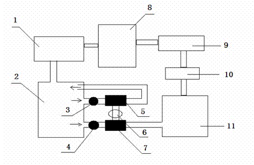
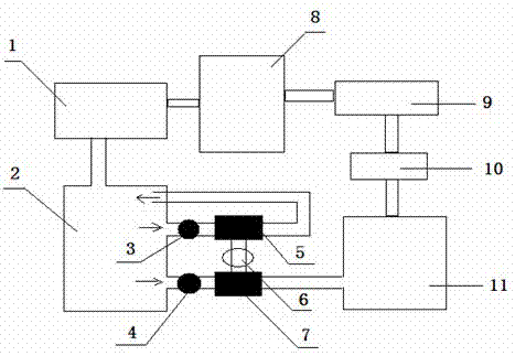
[0014] After the steam does work in the steam turbine 1, it forms exhausted steam and enters the condenser 2. The liquid that is cooled and dissipated is divided into two parts, and part of it is shunted by the circulating water pump 3, and the heat is extracted by the heat pump evaporator 5 to cool down, and then returns to the condensing steam. The other part is driven by the condensate pump 4 and heated by the heat pump radiator 7 to absorb heat, and then enters the low-pressure regenerative heater 11, the heat pump evaporator 5, the heat pump compressor 6, and the heat pump radiator 7 Constitute a heat pump cycle, steam turbine 1, condenser 2, low-pressure recuperation heater 11, deaerator 10, high-pressure recuperation heater 9, boiler 8 constitute a thermal power generation cycle, so that the heat of exhausted steam can be recovered , and keep the condens...


PUM


Abstract

The invention provides a special heat pump for a power plant. The condensed water in the condenser is divided into two parts, and a part is used as the heat source of the heat pump to extract heat. and cooling to maintain a lower saturated vapor pressure, and then form condensed water again, and the other part is used as the heated liquid of the heat pump, and the recovered heat is sent from the condensed water pump to the low-pressure heater, thereby performing heat recovery. The device of the present invention The beneficial effect is: the condensed water is divided into two parts as the heat source of the heat pump and the heated liquid, which can omit the external heat exchange structure of the current condenser, save water for cooling towers, reduce heat discharge and reduce heat exchange energy loss, At the same time, it can directly recover the heat of exhausted steam to improve the power generation efficiency, that is, compared with the current power generation level of 340 g / kW*, it can save 20-60 g / kW* of coal, and can also recover some low-grade heat .

Description

technical field [0001] The invention relates to a heat pump, especially a special heat pump for a power plant. Background technique [0002] The current thermal power plant is referred to as a thermal power plant. It is a factory that uses coal, oil, and natural gas as fuel to produce electric energy. Its basic production process is: the fuel is burned in a boiler to heat water to make steam, and the chemical energy of the fuel is converted into heat. The steam pressure drives the steam turbine to rotate, the heat energy is converted into mechanical energy, and then the steam turbine drives the generator to rotate, which converts the mechanical energy into electrical energy. [0003] Burning coal is transported from the coal yard to the coal scuttle by a coal conveyor belt. Large-scale thermal power plants burn pulverized coal to improve coal combustion efficiency. Therefore, the raw coal in the coal scuttle must first be sent to the coal mill to be ground into coal powder...

Claims


Application Information

Patent Timeline
Patent Type & Authority Applications(China)
IPC IPC(8): F25B30/06
CPCY02B30/52
Inventor 杨贻方
Owner 杨贻方
Why Eureka
Try Eureka