
The Machining Method of the Wear-resistant Layer on the Bottom Arc of the Connecting Rod in the Hydraulic Motor

A technology of hydraulic motor and processing method, which is applied in the field of processing the wear-resistant layer of the bottom arc surface of the connecting rod in the hydraulic motor, which can solve the problems of reliability and service life of the work, poor low-speed performance and starting performance of the motor, and the volume of the hydraulic motor. Problems such as heavy weight and so on, to achieve the effect of improving mechanical transmission efficiency, reducing material consumption, and improving bearing capacity

Inactive Publication Date: 2011-12-14
KUNSHAN JINFA HYDRAULIC MACHINERY
View PDF6 Cites 6 Cited by
  • Summary
  • Abstract
  • Description
  • Claims
  • Application Information

AI Technical Summary

Problems solved by technology

However, the specific pressure increases, the friction and wear are still serious, the mechanical efficiency is low, and the low-speed performance and starting performance of the motor are poor, and even glue failure occurs, which limits the further improvement of the motor pressure and speed.
In order to reduce the friction in the friction pair, the Italians changed the friction pair into a rolling bearing, which made the structure more complicated, and resulted in a larger volume and weight of the hydraulic motor, high manufacturing costs, and when the displacement of the motor is larger However, the reliability and lifespan problems of its work still cannot be solved.

Method used


Image

  • The Machining Method of the Wear-resistant Layer on the Bottom Arc of the Connecting Rod in the Hydraulic Motor
  • The Machining Method of the Wear-resistant Layer on the Bottom Arc of the Connecting Rod in the Hydraulic Motor
  • The Machining Method of the Wear-resistant Layer on the Bottom Arc of the Connecting Rod in the Hydraulic Motor

Examples


Embodiment 1

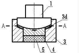
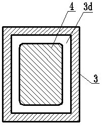
[0028] The metallurgical powder raw materials are prepared according to the weight percentage of copper 75%, tin 15%, and lead 10%, and the prepared mixture is put into a mixer and mixed uniformly to form a mixture. Put the mixed metallurgical powder mixture into the above-mentioned rectangular ring cavity 3d of the forming mold, and press the metallurgical powder mixture in the cavity 3d through the upper die 1 to form a rectangular ring-shaped wear-resistant layer 2 , The wear layer is 2.5mm, please refer to image 3 , Figure 4 .

[0029] Then the connecting rod is treated. First, remove the oxidized surface layer by pickling, use 15% dilute sulfuric acid solution, temperature 60℃, time 40 minutes; then use 8% NaOH solution or soda water for neutralization cleaning, neutralization cleaning time For 15 minutes, rinse with warm water and blow dry. Afterwards, electrolytic copper plating is performed, and a corresponding rectangular ring-shaped copper plating layer is formed...

Embodiment 2

[0033] The metallurgical powder raw materials are prepared according to the weight percentage of copper 80%, tin 12%, and lead 8%, and the prepared mixture is put into a mixer and mixed evenly to form a mixture. Put the mixed metallurgical powder mixture into the above-mentioned rectangular ring cavity 3d of the forming mold, and press the metallurgical powder mixture in the cavity 3d through the upper die 1 to form a rectangular ring-shaped wear-resistant layer 2 , The wear-resistant layer is 2.0mm, please refer to image 3 .

[0034] Next, the connecting rod is treated. First, remove the oxide surface layer by pickling, using 18% dilute sulfuric acid solution, temperature 50℃, time 35 minutes; then use 10% NaOH solution for neutralization and cleaning, and the neutralization cleaning time is For 18 minutes, rinse with warm water and blow dry. Afterwards, electrolytic copper plating is performed, and a corresponding rectangular ring-shaped copper plating layer is formed on ...

Embodiment 3

[0038] The metallurgical powder raw materials are prepared according to the weight percentage of copper 85%, tin 5%, and lead 10%, and the prepared mixture is put into a mixer and mixed evenly to form a mixture. Put the mixed metallurgical powder mixture into the above-mentioned rectangular ring cavity 3d of the forming mold, and press the metallurgical powder mixture in the cavity 3d through the upper die 1 to form a rectangular ring-shaped wear-resistant layer 2 , The wear layer is 2.2mm, please refer to image 3 .

[0039] Then the connecting rod is processed. First, remove the oxidized surface layer by pickling. Use a 20% dilute sulfuric acid solution at a temperature of 50°C for 30 minutes; then use a 12% NaOH solution for neutralization and cleaning. The neutralization cleaning time is For 20 minutes, rinse with warm water and blow dry. Afterwards, electrolytic copper plating is performed, and a corresponding rectangular ring-shaped copper plating layer is formed on th...


PUM


Abstract

The invention relates to a method for machining an abrasion resistance layer of a bottom curved surface of a connecting rod of a hydraulic motor. The method comprises the following steps of: 1) preparing a powder metallurgy material; 2) pressing the abrasion resistance layer; 3) removing an oxidized surface layer from the connecting rod; 4) forming a copper-plated layer on the bottom curved surface of the connecting rod; 5) welding the abrasion resistance layer to a position corresponding to the bottom curved surface of the connecting rod; and 6) sintering the abrasion resistance layer onto the bottom curved surface of the connecting rod. The method has the advantages that: the formed abrasion resistance layer has high abrasion resistance, heat resistance, friction reduction and wearing resistance performance, so that the hydraulic motor can keep long-term high lubrication performance and abrasion resistance performance during high speed running and has higher working reliability and service life; meanwhile, working resistance is reduced, the mechanical transmission efficiency is high and the bearing capacity of the motor is high; furthermore, material consumption of the abrasion resistance layer is reduced and the production cost is saved; and pollution to the environment caused by adopting babbitt metals is avoided.

Description

[0001] technical field [0002] The invention relates to a friction surface treatment method for a friction pair in a hydraulic motor, in particular to a processing method for a wear-resistant layer on the bottom arc surface of a connecting rod in a hydraulic motor. Background technique [0003] Due to the high operating frequency of the crankshaft and connecting rod in the hydraulic motor, the friction pair formed between the two is easy to wear. For this reason, the bottom of the connecting rod sliding shoe is usually coated with wear-resistant materials such as Babbitt alloy, and the static pressure is formed. support. However, the specific pressure increases, the friction and wear are still serious, the mechanical efficiency is low, and the low-speed performance and start-up performance of the motor are poor, and even gluing failure occurs, which limits the further improvement of the motor pressure and speed. In order to reduce the friction in the friction pair, the Ita...

Claims


Application Information

Patent Timeline
IPC IPC(8): B22F7/04
Inventor 徐祖悦穆金才杨正州徐成瞿丁发徐荣滨
Owner KUNSHAN JINFA HYDRAULIC MACHINERY
Learn More