Boiler wet slag removal system

A boiler and wet technology, applied in the field of boiler wet slag removal system, can solve the problems of endangering the safety of conveying equipment and operating personnel, poor adaptability to changes in boiler slag volume, and difficult control of operating parameters, etc., to achieve enhanced cracking effect and fuel saving Effects of reduction in consumption and floor space

Inactive Publication Date: 2011-12-21
CHINA POWER ENG CONSULTING GRP CORP EAST CHINA ELECTRIC POWER DESIGN INST
View PDF9 Cites 18 Cited by
  • Summary
  • Abstract
  • Description
  • Claims
  • Application Information

AI Technical Summary

Problems solved by technology

The main disadvantage of the dry slag removal system is that the important operating parameters of the system are not easy to control, and there are many deviations from the design values.
If the air volume for cooling the slag is too low and deviates from the design value, the temperature of the slag will be higher than 150°C to 200°C, and the insufficient cooling of the slag will endanger the safety of subsequent conveying equipment and operating personnel
If the air volume for cooling slag deviates too much from the design value, for example, it is higher than 1% to 1.5% of the total boiler air intake, the temperature of the air entering the boiler furnace will be lower than 250°C, resulting in unstable combustion of the boiler, and the proportion of cold air entering the furnace will be too high High, the efficiency of the boiler will decrease
In addition, the slag cooling of the dry slag removal system adopts natural air cooling, the cooling effect is poor, it is not easy to cool through the large slag, and the adaptability to the change of the amount of boiler slag is not strong

Method used


Image

  • Boiler wet slag removal system
  • Boiler wet slag removal system
  • Boiler wet slag removal system

Examples


no. 1 example

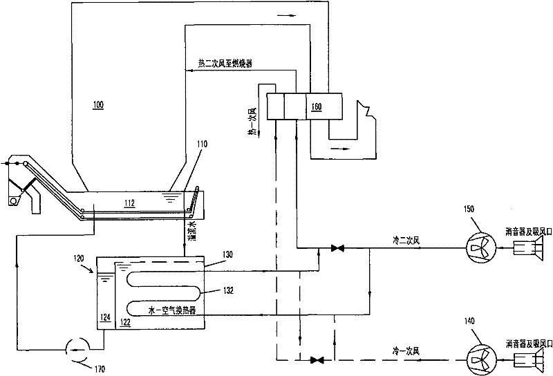
[0028] figure 1 The slag removal system of the first embodiment of the present invention is shown. refer to figure 1 As shown, in this embodiment, each boiler 100 is equipped with a water-immersed scraper slag extractor 110, an overflow water tank 120, a water-air heat exchanger 130, and a slag bin (not shown). The slag falls from the bottom of the boiler 100 through the slag well into the water-immersed scraper slag extractor 110, is cooled and cracked in the water tank 112 in the water-immersed scraper slag extractor 110, and then transported by the water-immersed scraper scraper extractor Enter the slag bin. During this process, the water in the tank of the water-immersed scraper scraper machine is heated by the slag.

[0029] An overflow port is arranged on the upper part of the water tank 112 of the water-immersed scraper scraper 110 , and the water in the water tank 112 passes through the overflow port, and the overflow water flows into the overflow water tank 120 . ...

no. 2 example

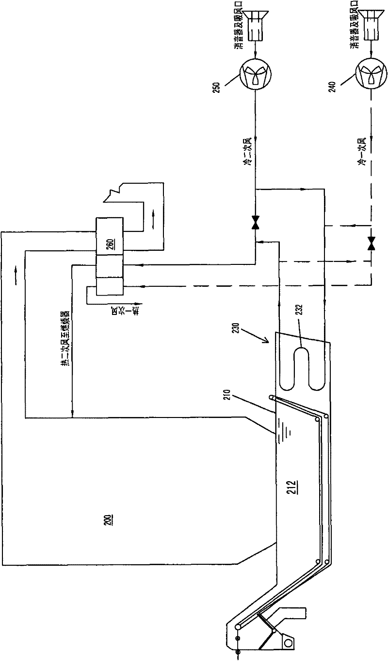
[0034] figure 2 The slag removal system of the first embodiment of the present invention is shown. refer to figure 2 As shown, in this embodiment, each boiler 200 is equipped with a water-immersed scraper slag extractor 210, a water-air heat exchanger 230, and a slag bin (not shown). The slag falls from the bottom of the boiler 200 through the slag well into the water-immersed scraper slag extractor 210, cools and cracks in the water tank 212 in the water-immersed scraper slag extractor 210, and then passes through the water-immersed scraper scraper extractor 210 Conveying into the slag bin. During this process, the water in the water tank 212 of the water-immersed scraper slag extractor is heated by the slag.

[0035]A water-air heat exchanger 230 is arranged on one side, or both sides, or the lower part, or other positions of the water tank 212 of the water-immersed scraper scraper machine, so that the heat exchanger and the water tank are integrated. The water side of...

no. 3 example

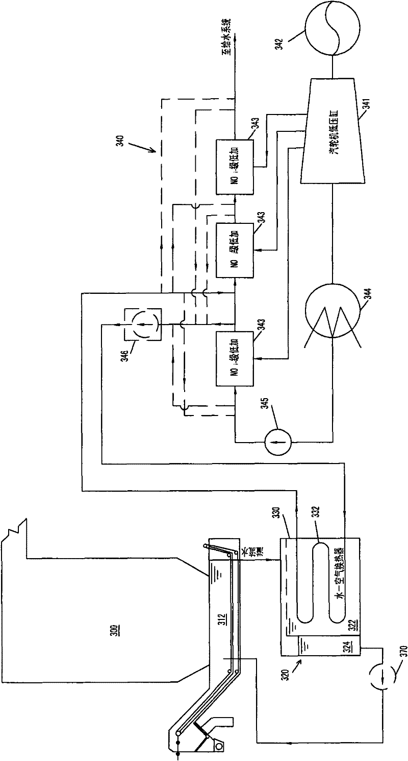
[0038] image 3 A slag removal system according to a third embodiment of the present invention is shown. refer to image 3 As shown, in this embodiment, each boiler 300 is provided with a water-immersed scraper slag extractor 310, an overflow water tank 320, a water-water heat exchanger 330, and a slag bin (not shown). The slag falls from the bottom of the boiler 300 through the slag well into the water-immersed scraper slag extractor 310, is cooled and cracked in the upper water tank 312 of the water-immersed scraper slag extractor, and then transported through the water-immersed scraper slag extractor 310 Enter the slag bin. During this process, the water in the water tank 312 of the water-immersed scraper slag extractor is heated by the slag.

[0039] The upper water tank 312 of the water-immersed scraper scraper 310 is provided with an overflow port, and the water in the water tank passes through the overflow port, and the overflow water flows into the overflow water ta...


PUM


Abstract

The invention relates to a boiler wet slag removal system, which comprises a slag extractor and a heat exchanger. The slag extractor is located under the boiler and has a water tank for receiving boiler bottom slag. The heat exchanger includes a heat exchange surface, one side of the heat exchange surface introduces the water in the water tank as the first heat exchange medium, and the other side of the heat exchange surface is the flowing second heat exchange medium to absorb the water in the water tank energy. In one solution of the present invention, the second heat exchange medium can be air, which is provided by the blower or the primary blower of the boiler, and is sent to the air preheater for the boiler together with the cold air of the blower or the primary blower after being heated . In another solution of the present invention, the second heat exchange medium can be condensed water, which is provided by one or more low-pressure heaters of the steam turbine condensate system, and is heated and delivered to one or more low-pressure heaters . In this way, the waste heat of the slag can be recovered, which simplifies the structure of the wet slag removal system and reduces the water consumption.

Description

technical field [0001] The invention relates to slag removal for coal-fired boilers, in particular to a boiler wet slag removal system. Background technique [0002] For the boiler mechanical slag removal system in thermal power plants, the following two technologies are widely used at present, one is the wet slag removal system using the scraper slag remover, the other is the air-cooled dry slag removal system using the steel belt slag remover system. [0003] The equipment of the wet slag removal system of scraper slag machine mainly consists of water-immersed scraper slag machine, slag conveying equipment from slag machine to slag bin, slag bin, overflow pool, sedimentation tank, buffer pool and related cold slag Water pumps, flushing water pumps, sewage pumps, slag system make-up pumps, etc. Boiler bottom slag falls from boiler slag outlet and slag well into the upper water tank of the scraper slag extractor. After being cooled and cracked by the water in the water tan...

Claims


Application Information

Patent Timeline
Patent Type & Authority Applications(China)
IPC IPC(8): F23J1/06F23L15/00F01D15/10
CPCY02E20/34
Inventor 高玮叶勇健
Owner CHINA POWER ENG CONSULTING GRP CORP EAST CHINA ELECTRIC POWER DESIGN INST
Why Eureka
Try Eureka