
Thermoelectric power generation device implemented on driving vehicles

A technology for thermoelectric power generation and transportation, which is applied to generators/motors, electrical components, etc., can solve the problems of increased power consumption, high production and installation requirements, and complicated production and processing of exhaust pipes, and achieves high power generation efficiency and heat dissipation efficiency. high effect

Inactive Publication Date: 2011-12-21
赵蒙
View PDF8 Cites 13 Cited by
  • Summary
  • Abstract
  • Description
  • Claims
  • Application Information

AI Technical Summary

Problems solved by technology

[0003] CN201332370Y discloses a device for thermoelectric power generation using the exhaust pipe exhaust gas of a vehicle. The thermoelectric power generation sheet, heat sink, and heat insulation section of the device are closely matched with the square exhaust tube to form a whole. The deficiency of the device is that the exhaust pipe is produced Complex processing, increased weight and cost, inconvenient installation, maintenance and repair, and when the exhaust pipe is replaced, the thermoelectric power generation system needs to be replaced at the same time, and the operating cost is high, so the actual utilization rate is not high
[0004] CN200997576Y discloses another device for thermoelectric power generation using the exhaust temperature of the exhaust pipe of a vehicle. The device directly lays an arc-shaped thermoelectric power generation sheet on the outer wall of the exhaust pipe. It has high production and installation requirements, poor stability, and low temperature The surface heat dissipation performance is poor, and the power generation efficiency is not high in actual use
[0005] CN200997575Y discloses a device that utilizes the water temperature of the water tank of a vehicle to realize thermoelectric power generation. The device is to directly install a thermoelectric power generation sheet on the windward surface of the water tank. The natural wind cooling function when the vehicle is running, the heat dissipation is not smooth, the water temperature in the water tank rises rapidly, resulting in the reduction of the cooling function of the water tank, and the cooling fan is in working condition for a long time
The fan is in the working state for a long time, otherwise it will lead to an increase in power consumption

Method used


Image

  • Thermoelectric power generation device implemented on driving vehicles
  • Thermoelectric power generation device implemented on driving vehicles
  • Thermoelectric power generation device implemented on driving vehicles

Examples


Embodiment 1

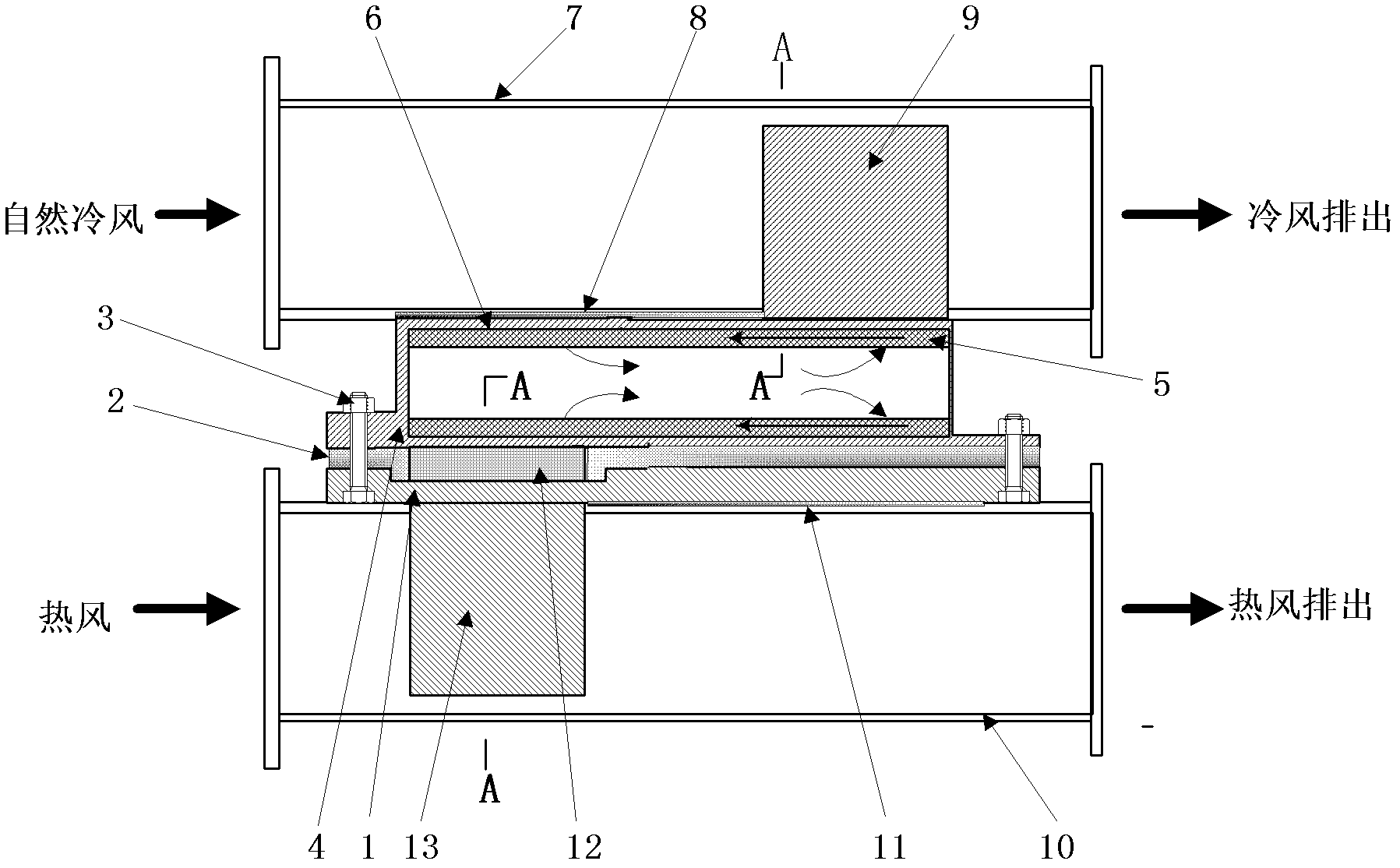
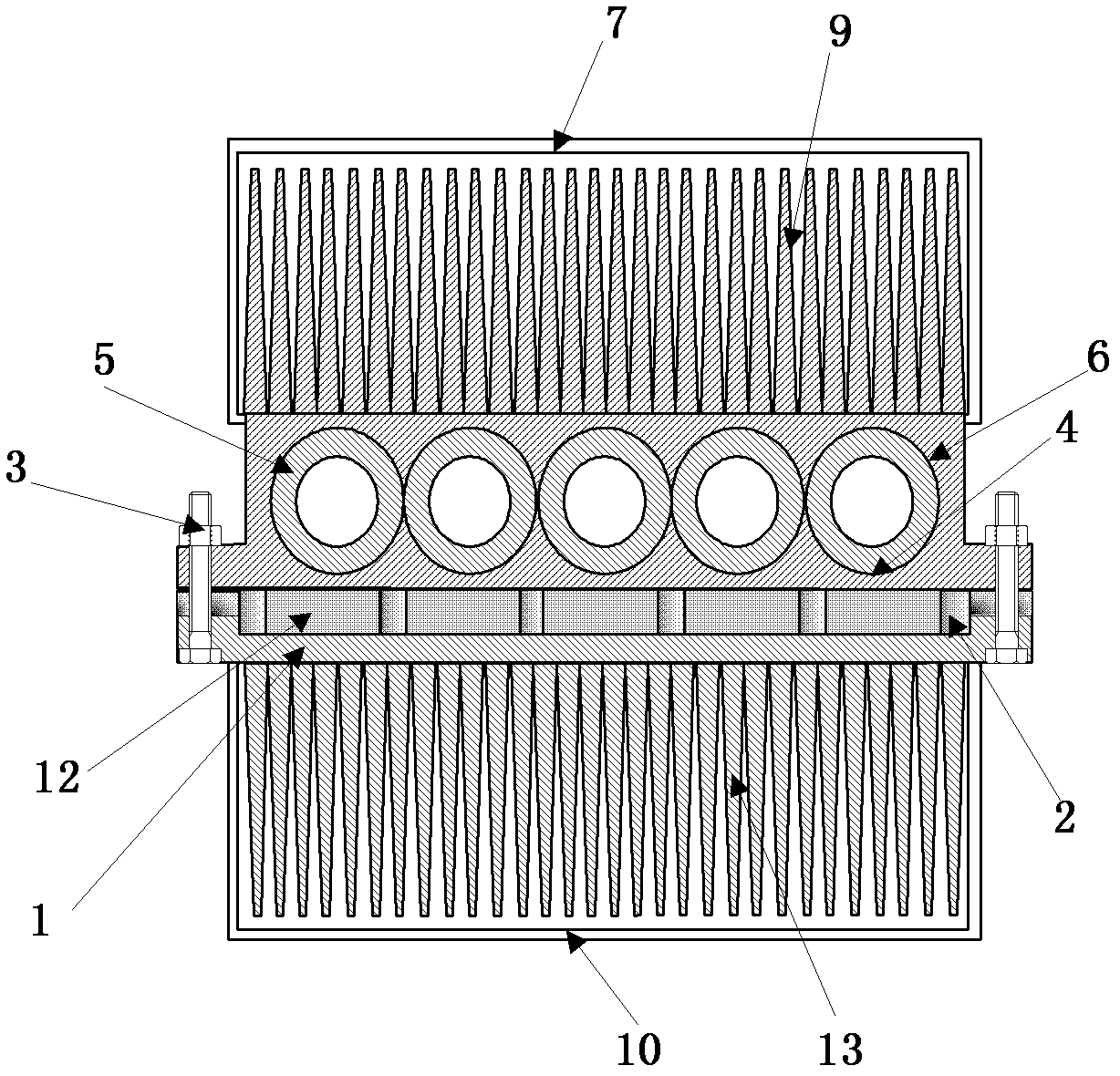
[0027] The thermoelectric power generation device implemented on the driving vehicle disclosed in this embodiment, its structure is as follows: figure 1 And attached figure 2As shown, the exhaust gas emitted by the vehicle engine is used for thermoelectric power generation. Its composition includes a device body, a thermoelectric power generation sheet assembly 12 installed on the device body, a heat pipe and a radiator. The device body is a split structure, one part is the heat collecting end 1 of the device body, and the other part is the heat dissipation end 4 of the device body. The thermoelectric power generation sheet assembly 12 is located between the heat collecting end and the heat dissipation end of the device body. It is opposite to the heat collecting end of the device body, and the low temperature end is opposite to the heat dissipation end of the device body. The thermoelectric power generation sheet assembly is fixed between the two parts of the device body th...

Embodiment 2

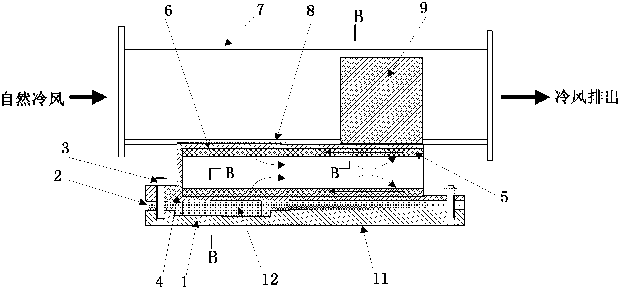
[0030] The thermoelectric power generation device implemented on the driving vehicle disclosed in this embodiment, its structure is as follows: image 3 And attached Figure 4 As shown, the heat dissipated by the engine body of the vehicle is used for thermoelectric power generation. The basic structure of this thermoelectric power generation device is the same as that of Embodiment 1, except that the heat collecting end of the device body is directly fixed on the engine body, and the heat collector part in Embodiment 1 is omitted.

Embodiment 3

[0032] The thermoelectric power generation device disclosed in this embodiment implemented on a moving vehicle uses the hot gas at a relatively high temperature in the engine compartment of the vehicle to perform thermoelectric power generation. The basic structure of this thermoelectric power generation device is substantially the same as that of Embodiment 1, except that the heat pipe and the radiator are different. The pipe body of the heat pipe is not a straight pipe, but a curved pipe. The cooling fins of the radiator are directly welded on the heat pipe condensation section Structures on the body wall.


PUM


Abstract

The invention discloses a thermoelectric power generation device implemented on a driving vehicle, which comprises a device body, a thermoelectric power generation chip assembly installed on the device body, a radiator and a heat pipe, and a heat collector between the high temperature end of the thermoelectric power generation chip component and the device body The low temperature end is connected with the heat dissipation end of the device body. The radiator is composed of a number of heat dissipation fins fixed at one end and a tube surrounding the heat dissipation fins. At the heat dissipation end of the device body, the condensation section is fixedly connected with the heat dissipation fin base. The invention adopts the advanced heat pipe heat dissipation technology, skillfully utilizes the high-speed natural cold wind generated by the vehicle to dissipate heat, has the characteristics of good heat dissipation performance, high thermoelectric conversion efficiency, reasonable structure design, good installation adaptability, convenient disassembly, maintenance and repair, and can Use vehicle engine exhaust gas, hot air in the cabin, high temperature on the roof in summer, etc. to generate temperature difference power generation.

Description

technical field [0001] The invention relates to a power generating device, in particular to a power generating device which utilizes natural wind and heat generated by the vehicle itself to generate direct current through a thermoelectric power generation sheet assembly. It belongs to the technology of energy recovery and regeneration. Background technique [0002] With the development of the economy, the penetration rate and utilization rate of automobiles are getting higher and higher. The automobiles powered by gasoline engines and diesel engines consume more and more oil and cause more and more serious pollution to the environment. In order to reduce the dependence and consumption of oil and protect the environment, more and more attention has been paid to the research and development of new energy sources. Among them, the waste gas (up to 600°C) generated by vehicles such as automobiles and trains, and the hot air in the cabin (which is also several times higher than th...

Claims


Application Information

Patent Timeline
IPC IPC(8): H02N11/00
Inventor 赵蒙
Owner 赵蒙
Learn More