power converter

A technology of power converters and transformers, which is applied in the direction of high-efficiency power electronic conversion, electrical components, and conversion equipment without intermediate conversion to AC. It can solve problems such as increased pressure, increased EMI, and poor energy efficiency, and achieves the overall structure Effects of reducing, reducing switching devices, and reducing costs

Active Publication Date: 2011-12-28
安徽泰尼科技有限公司
View PDF3 Cites 19 Cited by
  • Summary
  • Abstract
  • Description
  • Claims
  • Application Information

AI Technical Summary

Problems solved by technology

The defects of the technical solution of the above-mentioned patent application are: 1. The input surge problem of traditional AC / DC is not solved, and the input surge is still treated passively, which not only increases the cost, but also reduces the energy efficiency and brings additional EMI problem
2. The energy efficiency of AC / DC is mainly affected by the switching loss and conduction loss of the switching tube and the copper loss and iron loss of the magnetic material; the direct and effective way to solve the loss of the switching tube is to reduce the number of switching tubes; and the The number of switching tubes in the patent application is large, so its energy efficiency is poor; 3. It cannot improve the life of AC / DC products, because the solution to the life of AC / DC products is the life of the storage electrolytic capacitor of PFC. From the overall control method, it is only in The simple method of reducing the voltage of the PFC when the load voltage is low does not coordinate and control the duty cycle of the PFC and the duty cycle of the DC / DC as a whole; The design of the design, there is a peak current between the conduction, which increases the EMI, and also increases the processing cost and difficulty of the power factor of the subsequent stage, and the system design of each link of the AC / DC power supply cannot be realized; the interval generated in the rectification part The summit is brought to the PFC link, which increases the implementation cost of the PFC link and its own power consumption, noise, etc., and will be brought to the DC / DC link together, thus increasing the subsequent implementation pressure

Method used


Image

  • power converter
  • power converter
  • power converter

Examples


Embodiment Construction

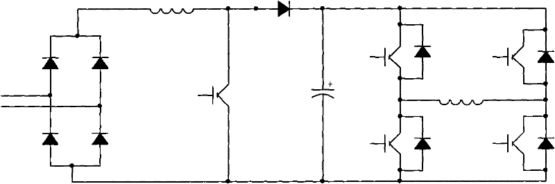
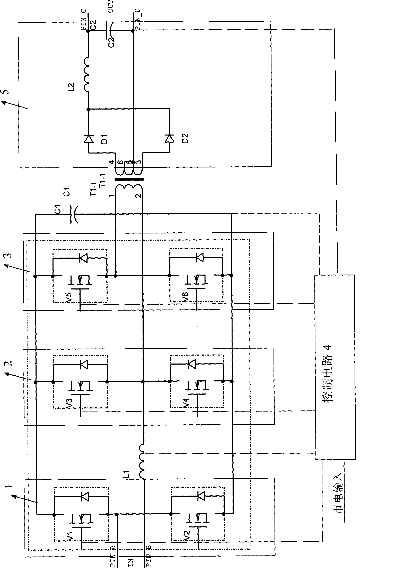
[0027] refer to image 3 , shows a schematic circuit diagram of the power converter of the present invention. Wherein, the power converter includes a first bridge arm 1, a second bridge arm 2 and a third bridge arm 3, a capacitor C1, a control circuit 4, a transformer T1 and a DC output circuit 5; wherein the first bridge arm 1 is composed of two The switch tubes V1 and V2 are connected in series; the second bridge arm 2 is formed by connecting two switch tubes V3 and V4 in series; the third bridge arm 3 is formed by connecting two switch tubes V5 and V6 in series; the first bridge arm 1 and the first bridge arm 1 The second bridge arm 2 and the third bridge arm 3 are connected in parallel and then connected in parallel with the capacitor C1; between the midpoint of the first bridge arm 1 and the second bridge arm 2, there is a commercial power input terminal and an inductance L1 in series; The primary side of the transformer T1 is connected in series between the middle point...


PUM


Abstract

The invention relates to a power converter, which is composed of three bridge arms connected in parallel and then connected in parallel with a working capacitor; and between the midpoints of the first bridge arm and the second bridge arm, there is a commercial power input and an inductance connected in series, and the second bridge arm The primary side of the transformer is connected in series between the midpoint of the arm and the third bridge arm, and the negative side of the transformer is connected to the DC output circuit; the control terminals of the first bridge arm, the second bridge arm, and the third bridge arm are all connected to the control circuit The control signal is connected; wherein the control circuit selectively controls the conduction of the switch tube corresponding to the first bridge arm and the second bridge arm according to the detection result of the zero-crossing voltage input by the mains to perform power factor correction. The control circuit also detects the load The operating state parameters selectively control the conduction of the switch tube of the third bridge arm to output energy to the secondary side of the transformer so that the DC output circuit outputs DC; the present invention combines AC anti-surge, rectification and filtering, PFC conversion, DC/ The DC is designed together, and only six switching tubes are used to complete the power conversion.

Description

technical field [0001] The invention relates to a power conversion circuit, in particular to a power converter with double H-type topological structure. Background technique [0002] The current product form of power supply products is a power conversion device that combines a control chip with a topological structure to achieve a certain output voltage and current requirements. That is to say, a set of hardware products can only realize a specific function. At present, some digitally controlled power supplies are only realized by changing all or part of the traditional analog control method to software control. In system communication, There is some flexibility in managing and modifying output parameters. [0003] In the technical design of power converters, a mathematical topology needs to be selected for certain input voltage, output voltage, current, and power requirements. Currently, commonly used topologies include BUCK, BOOST, BUCK BOOST, SEPIC, and FLYBACK , FORWAR...

Claims


Application Information

Patent Timeline
Patent Type & Authority Applications(China)
IPC IPC(8): H02M7/217H02M3/07H02M1/42
CPCY02B70/126Y02B70/10
Inventor 盛飞
Owner 安徽泰尼科技有限公司
Why Eureka
Try Eureka