Treatment method for stinky waste gas discharged by storage tank

A treatment method and waste gas treatment device technology, applied in separation methods, chemical instruments and methods, and dispersed particle separation, etc., can solve problems such as poor stability, tail gas discharge that cannot meet standards, and stricter requirements, and achieve high absorption efficiency. Recycling and discharge of other impurities, and the effect of improving the treatment rate

Active Publication Date: 2014-04-16
CHINA PETROLEUM & CHEM CORP +1
View PDF9 Cites 0 Cited by
  • Summary
  • Abstract
  • Description
  • Claims
  • Application Information

AI Technical Summary

Problems solved by technology

This treatment process is technologically reasonable, because removing hydrogen sulfide and some mercaptans with lye can avoid the influence of these substances on the subsequent treatment process, but the stability of this treatment process is slightly poor during operation. The requirements for the follow-up treatment process are relatively strict, and the final tail gas sometimes fails to meet the emission standards

Method used


Image

  • Treatment method for stinky waste gas discharged by storage tank
  • Treatment method for stinky waste gas discharged by storage tank
  • Treatment method for stinky waste gas discharged by storage tank

Examples


Embodiment 1

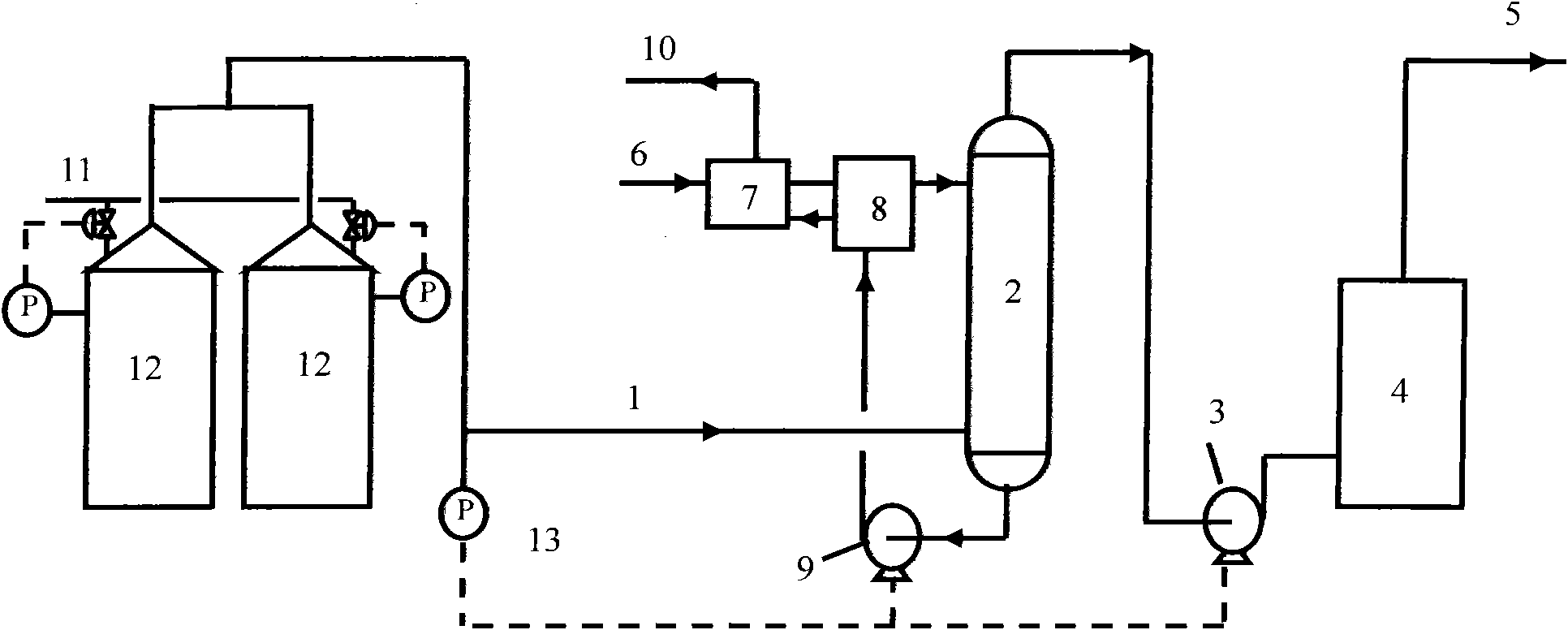
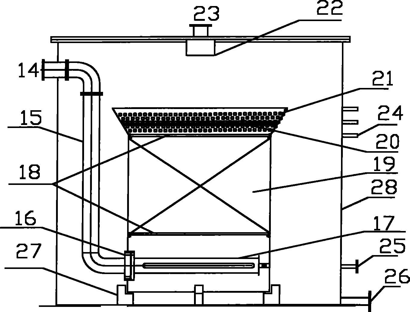
[0049] Hydrogen sulfide 5000mg / m3 in waste gas from sour water tank area of ​​an oil refinery 3 , dimethyl disulfide 100mg / m 3 , thiophene 60mg / m 3 , total hydrocarbon concentration 20×10 4 mg / m 3 , the flow rate is 100Nm 3 / h. use as figure 1 In the process flow shown, the exhaust gas is discharged intermittently. When the pipeline pressure is greater than 1000Pa, the gas delivery pump 3 is started and the rich absorption oil pump 9 and the refrigeration unit 8 are started at the same time. The desulfurization reactor adopts such as image 3 In the structure shown, the sodium hydroxide aqueous solution is used as the desulfurization absorption liquid in the desulfurization reactor, and fresh lye is replaced when the pH value of the working liquid drops to 9. The absorption tower is filled with Dg38 packing ring. The absorbent adopts catalytic cracking gas oil fraction with a distillation range of 180-380°C, and the sulfur content is 0.8% based on sulfur mass. The low-t...

Embodiment 2

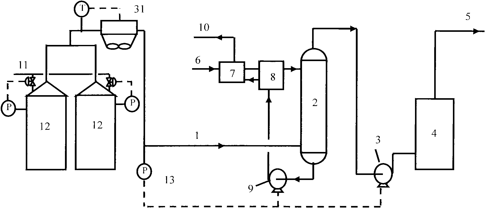
[0052] Hydrogen sulfide 1000mg / m3 contained in waste gas from a waste oil tank area of ​​an oil refinery 3 , dimethyl disulfide 300mg / m 3 , methyl mercaptan 60mg / m 3 , total hydrocarbon concentration 20×10 4 mg / m 3 , the flow rate is 150Nm 3 / h. During operation, 1000m3 / h of water vapor purge gas is intermittently sent into the storage tank, such as figure 2 In the process flow shown, the waste gas condenser is an air cooler. When a large amount of waste gas is discharged, the temperature of the waste gas in the discharge pipe is higher than 60°C. At this time, the fan of the air cooler is started, and the air cooler starts to run. When the pressure of the pipe is greater than 30000Pa, the gas delivery pump 3 is started and the rich absorption oil pump 9 and the refrigeration unit 8 are started at the same time. , the absorbent is FCC diesel with a sulfur content of 1.2%, and the desulfurization reactor adopts such as image 3 In the structure shown, sodium hydroxide s...


PUM


Abstract

The invention discloses a treatment method for stinky waste gas discharged by a storage tank. The stinky waste gas discharged by the storage tank comprises hydrocarbons, hydrogen sulfide, organic sulfides and the like; the discharged waste gas is introduced into a waste gas treatment device; when the waste gas treatment device runs, the waste gas first passes through a low-temperature absorption tower; distillate is used as an absorbent, and the distillate is cooled to the temperature of between 10 DEG C below zero and 30 DEG C in a cooler; after the waste gas is absorbed by the distillate, most hydrocarbons and most organic sulfides are purified; and the waste gas passing through the absorption tower is purified in a circulation desulfurization reactor, the sulfur compounds of the waste gas are further absorbed by using an alkali liquor absorbent in the circulation desulfurization reactor, and the purified gas passing through the circulation desulfurization reactor is discharged by a discharge tube. The treatment method has the advantages of simple flow, easily obtained absorbent, high purification efficiency and the like, and is suitable for treating respiratory gas of various chemical storage tanks.

Description

technical field [0001] The invention relates to a method for treating foul-smelling waste gas discharged from storage tanks, especially organic sulfides such as hydrogen sulfide, mercaptan, and sulfide discharged from sulfur-containing sewage tanks, waste oil tanks, semi-finished oil tanks and other refinery equipment in oil refineries. A combined treatment method of physical purification and chemical purification of malodorous exhaust gas with harmful components such as hydrocarbons. Background technique [0002] In the process of crude oil processing in refineries, some facilities inevitably emit a large amount of odorous and polluting waste gas, especially facilities such as sulfur-containing sewage storage tanks, semi-finished oil storage tanks, dirty oil storage tanks, and sweetening tail gas. These facilities discharge The malodorous pollutants include hydrogen sulfide, organic sulfides, benzene series and other VOCs (volatile organic compounds). Long-term activities ...

Claims


Application Information

Patent Timeline
Patent Type & Authority Patents(China)
IPC IPC(8): B01D53/78B01D53/14B01D53/52B01D53/72
Inventor 郭兵兵王海波朴勇刘忠生方向晨刘璐
Owner CHINA PETROLEUM & CHEM CORP
Why Eureka
Try Eureka