FPGA (field-programmable gate array) interconnection structure supporting time division switching

A technology of time-division switching and interconnection structure, applied in the FPGA field, can solve problems such as difficult implementation, slow logic circuit performance, increased chip area and power consumption, etc., to solve scalability problems, solve signal stability, and reduce design complexity sexual effect

Inactive Publication Date: 2012-02-01
FUDAN UNIV
View PDF2 Cites 8 Cited by
  • Summary
  • Abstract
  • Description
  • Claims
  • Application Information

AI Technical Summary

Problems solved by technology

However, these improvements are all improvements in the spatial structure. After more than 20 years of development of FPGA, from the characteristics that the mainstream product structures of several large FPGA manufacturers tend to be similar, it can be seen that the spatial structure should be done under the traditional structure. It's getting harder and harder to make breakthrough improvements
[0008]The logic circuit performance implemented by FPGA is often several times slower than that implemented by ASIC, because the complex interconnection structure of FPGA brings a lot of delay, literature [8~9] Some pipeline interconnect resource structures are proposed, the purpose of which is to reduce interconnect delay and speed up through pipeline technology, at the cost of adding registers to interconnect resources, increasing chip area and power consumption
At the same time, after the pipeline interconnection is adopted, the clock delay of the local circuit will be increased. In order to ensure the correctness of the global function, it is necessary to add corresponding clock delay units on other paths. This process is called retiming. The price is to increase the clock delay of the input and output of the circuit
[0009] Generally, the clock frequency of FPGA is relatively low when us

Method used


Image

  • FPGA (field-programmable gate array) interconnection structure supporting time division switching
  • FPGA (field-programmable gate array) interconnection structure supporting time division switching
  • FPGA (field-programmable gate array) interconnection structure supporting time division switching

Examples


Example Embodiment

[0059] The solution of the present invention will be further described below in conjunction with the drawings and specific embodiments.

[0060] In order to enable the traditional FPGA structure to support time division switching, several major changes need to be made to the existing traditional FPGA structure:
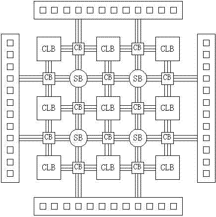
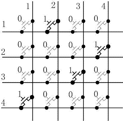
[0061] The traditional FPGA interconnection resources are composed of CB and SB. The horizontal and vertical wiring channels are connected through the switch box SB, and the input and output of the CLB are connected with each wiring channel through the connection box CB. Both CB and SB in the traditional FPGA structure adopt a spatial exchange structure, and the control switches are all composed of transmission tubes or MUX (multiplexers) composed of transmission tubes, such as Figure 8 Shown.

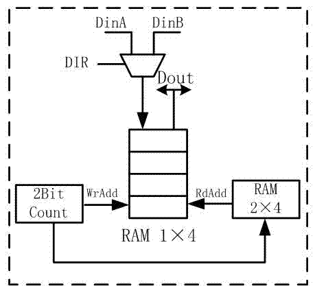
[0062] The invention converts the interconnection parallel signals in the FPGA into serial signals, which can reduce the number and area of ​​interconnection resources in the FPGA, ...


PUM


Abstract

The invention belongs to the technical field of an FPGA (field-programmable gate array) and in particular relates to an FPGA interconnection structure supporting the time division switching. On the basis of the structure of an assembly line, time division multiplexing and source-synchronous interconnection, the time slot switching principle which is commonly used in a communication system is combined for providing a novel FPGA interconnection resource structure, the time division switching is used for replacing an original traditional space switching interconnection structure, and the structure adds part of time slot switching on a switching matrix in time division multiplexing interconnection resources, thereby being capable of greatly simplifying the switching matrix and the design of an input and output selector. The novel FPGA interconnection structure can reduce the area of the interconnection resources and improve the logic density of the FPGA, and has the characteristics of being high in performances, reducing the complexity in design, improving the reliability and being low in power consumption.

Description

technical field [0001] The invention belongs to the field of FPGA technology, and in particular relates to an FPGA interconnection structure supporting time-division switching. Background technique [0002] FPGA (Field Programmable Gate Array) is a field programmable gate array. It is a product of further development on the basis of PAL, GAL, EPLD and other programmable devices. Its appearance not only solves the shortcomings of custom circuits, but also overcomes the original The disadvantage of programmable circuit programming points is limited. At present, FPGA has been listed as the three core chips together with ASIC and ASSP. [0003] Since Xilinx launched the first Field Programmable Gate Array FPGA chip in 1985, FPGA has experienced more than 20 years of development. With the continuous advancement of process technology and the innovation of solutions, FPGA's breakthroughs in logic density, performance, power consumption, cost, etc. have expanded its application fi...

Claims


Application Information

Patent Timeline
IPC IPC(8): H03M9/00
Inventor 余慧陈利光陈更生
Owner FUDAN UNIV
Why Eureka
Try Eureka