Simultaneous desulfuration and denitration method for smoke by combining photocatalytic oxidation with ammonia method

A photocatalytic oxidation, desulfurization and denitrification technology, applied in the field of flue gas purification, can solve the problems of large investment and difficulty in widespread implementation, and achieve the effects of improving economic benefits, low cost, and reducing operating costs

Inactive Publication Date: 2012-02-15
湖南湘达环保工程有限公司
View PDF4 Cites 8 Cited by
  • Summary
  • Abstract
  • Description
  • Claims
  • Application Information

AI Technical Summary

Problems solved by technology

However, the SCR denitrification method requires a large investment and is difficult to implement widely.

Method used


Image

  • Simultaneous desulfuration and denitration method for smoke by combining photocatalytic oxidation with ammonia method
  • Simultaneous desulfuration and denitration method for smoke by combining photocatalytic oxidation with ammonia method

Examples


Embodiment 1

[0028] With butyl titanate as precursor and ethanol as solvent, Fe(NO 3 ) 3 Introducing dopant ions to prepare Fe by sol-gel method 3+ -TiO 2 The photocatalyst gel was calcined to 550 °C for 3 h to prepare photocatalyst particles. The photocatalyst is supported by a photocatalyst-coated steel plate. The specific process includes: using a stainless steel plate as a substrate, placing SiO 2 After the adhesive and inorganic pigments form the bottom layer, SiO2 is coated on it. 2 Adhesives and Fe-containing 3+ Doped TiO 2 The photocatalyst layer is baked and coated to prepare a photocatalyst-coated steel sheet. Among them, the customized specifications of the stainless steel plate can be 2438 mm × 200 mm × 1 mm.

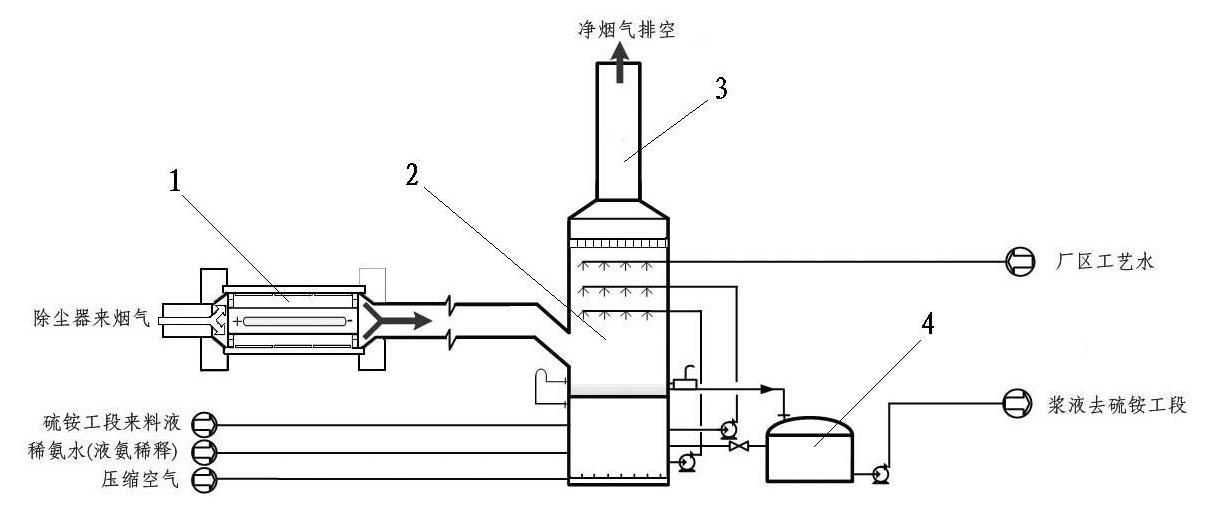
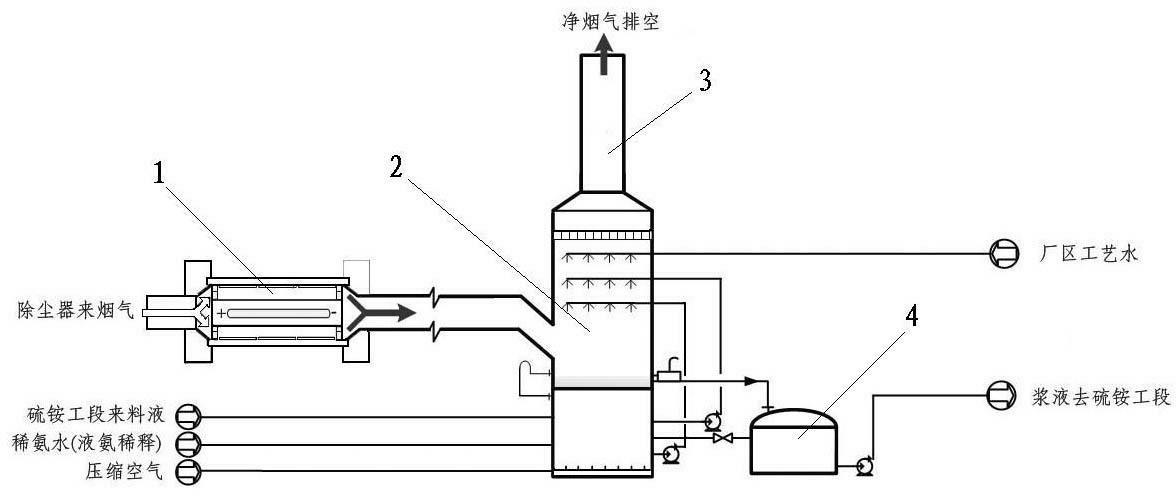
[0029] The photocatalyst with the above-mentioned coated steel plate fixed on the inner wall is installed between the boiler flue outlet and the desulfurization tower, such as figure 1 shown. The original flue gas volume of the boiler is 490,000 Nm 3 / h (wet b...

Embodiment 2

[0031] The photocatalyst adopts the P25 photocatalyst produced by Degussa, and the photocatalyst is coated on the steel plate. The specific process includes: using a stainless steel plate as a substrate, placing SiO2 After the adhesive and inorganic pigments form the bottom layer, SiO2 is coated on it. 2 The adhesive and the P25 photocatalyst layer are baked and coated to prepare the photocatalyst-coated steel plate.

[0032] Install the photocatalyst coated steel plate prepared above on the inner wall of the photocatalyst, such as figure 1 shown. When the original flue gas volume is 360,000 Nm 3 / h (wet basis), the sulfur content is 6000 mg / Nm 3 , with a nitrogen content of 600 mg / Nm 3 When using 20 wt% ammonia water as the ammonia source, the ammonia water consumption is about 5.9 t / h. The output of the by-product ammonium sulfate ammonium nitrate compound fertilizer is 3.8 t / h, the desulfurization rate reaches 98.5%, and the denitrification rate reaches 70%.


PUM


Abstract

The invention discloses a simultaneous desulfuration and denitration method for smoke by combining photocatalytic oxidation with an ammonia method, which is characterized in that boiler smoke firstly enters a photocatalytic reactor; NOx in the smoke is oxidized to generate NO2; smoke subsequently enters an ammonia method desulfurizing tower for inverse contact with desulfurizing agent solution; and SO2 and NO2 are further deeply removed. The photocatalytic reactor mainly comprises a reaction chamber and a light source system positioned in the middle comprises a high-voltage mercury lamp of which the power is above 125W and a quartz glass sleeve. Compared with the traditional SCR (Selective Catalyctic Reduction) denitration method, the simultaneous desulfuration and denitration method is characterized in that the problems of large land occupation, big investment, high operation cost, big possibility of scaling, blocking and positioning for cellular catalyst and the like in the SCR denitration method can be solved, the denitration problem can be solved, desulfuration and denitration are simultaneously carried out, desulfuration efficiency is above 95%, and denitration efficiency is above 70%. Denitration equipment can be constructed without large investment. Cost is low, operation cost is greatly lowered, and economic benefit is improved.

Description

technical field [0001] The invention relates to the technical field of flue gas purification, in particular to a method for synchronous desulfurization and denitrification of flue gas photocatalytic oxidation combined with ammonia method, which belongs to the engineering problem of synchronous desulfurization and denitrification of flue gas. Background technique [0002] Coal combustion releases a large amount of CO 2 , SOx, NOx, particle pollutants and trace heavy metal pollutants have caused serious air pollution. Acid gas pollution has become a burden on China's economic and social development. During the 11th Five-Year Plan period, the country vigorously promoted the desulfurization process, and successively built some industrial-scale treatment devices, which achieved remarkable results. At the same time, another major problem in air pollution, that is, the pollution of nitrogen oxides (NOx) has been paid more and more attention, and the research and development of NO...

Claims


Application Information

Patent Timeline
Patent Type & Authority Applications(China)
IPC IPC(8): B01D53/75B01D53/86B01D53/78B01D53/60C05C13/00
CPCY02A50/20
Inventor 周元金彭献忠熊绍锋
Owner 湖南湘达环保工程有限公司
Why Eureka
Try Eureka