Gas combustion-supporting device of recirculating fluidized bed and combustion control device of recirculating fluidized bed

A technology of circulating fluidized bed and control system, which is applied in the direction of fluidized bed combustion equipment, fuel for combustion in a molten state, and combustion methods, etc. Reduce the cost of tail gas treatment, solve the problem of land occupation, and achieve good comprehensive benefits

Inactive Publication Date: 2012-02-15
北京君达能源投资有限公司
View PDF7 Cites 8 Cited by
  • Summary
  • Abstract
  • Description
  • Claims
  • Application Information

AI Technical Summary

Problems solved by technology

[0007] The technical problem to be solved by the present invention is to provide a circulating fluidized bed gas combustion device and a circulating fluidized bed combustion control system to overcome the high carbon dioxide emissions caused by adding coal to the combustion chamber in the prior art , high coal consumption, high cost of electricity, high cost of tail gas treatment, and cinders are easy to agglomerate, resulting in wear of the circulating fluidized bed furnace, and the large amount of waste slag discharge makes the treatment more difficult and other defects

Method used


Image

  • Gas combustion-supporting device of recirculating fluidized bed and combustion control device of recirculating fluidized bed
  • Gas combustion-supporting device of recirculating fluidized bed and combustion control device of recirculating fluidized bed
  • Gas combustion-supporting device of recirculating fluidized bed and combustion control device of recirculating fluidized bed

Examples


Embodiment Construction

[0026] The specific implementation manners of the present invention will be further described in detail below in conjunction with the accompanying drawings and embodiments. The following examples are used to illustrate the present invention, but are not intended to limit the scope of the present invention.

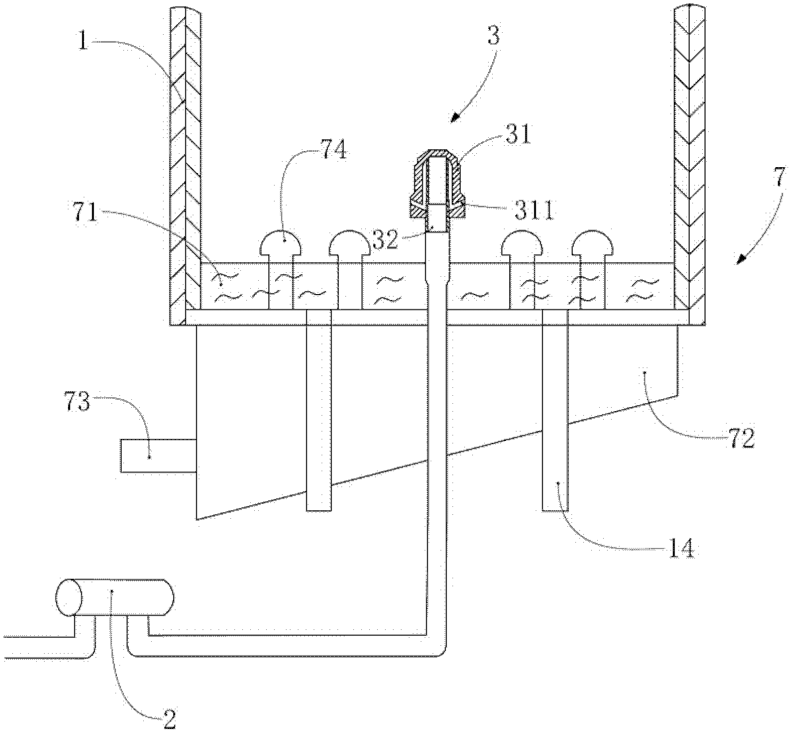
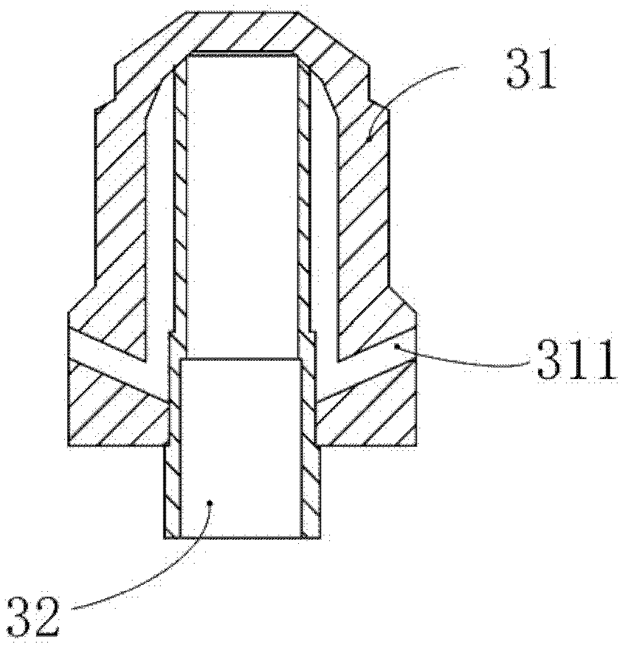
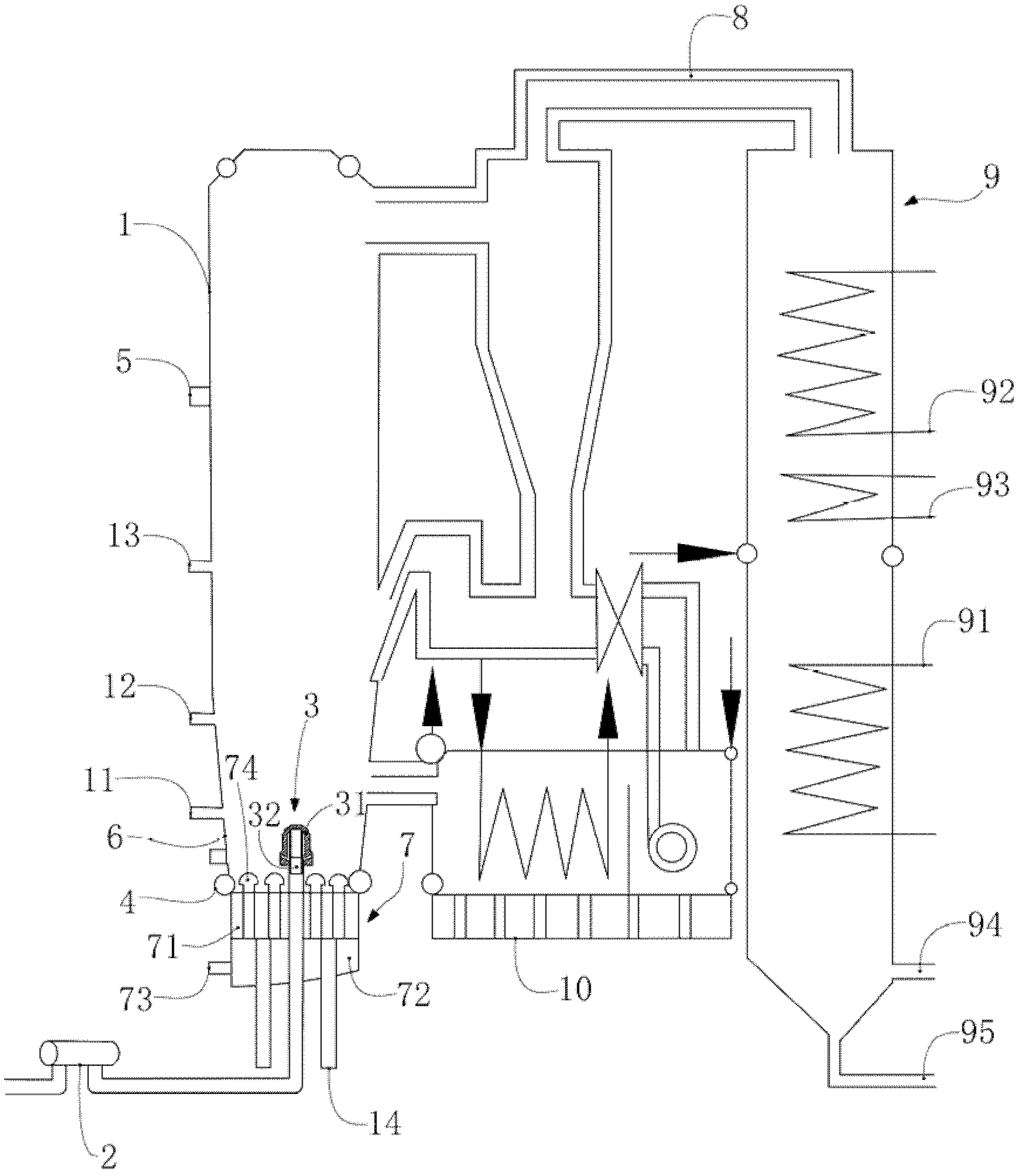
[0027] Such as Figure 1-2 As shown, the circulating fluidized bed gas combustion-supporting device in the embodiment of the present invention includes a fluidized bed combustion chamber 1, a gas compression device 2 and a gas compression injector 3. The gas compression device 2 communicates with the fluidized bed combustion chamber 1 through a pipeline, Gas is introduced into the fluidized bed combustion chamber 1 . A gas compression injector 3 is installed on the top of the pipeline. In this embodiment, the gas compression device 2 is a compressor, and the gas that is compressed by the compressor and passed into the fluidized bed combustion chamber 1 is biogas, natural...


PUM


Abstract

The invention relates to the technical field of fluidized bed combustion, and in particular relates to a gas combustion-supporting device of a recirculating fluidized bed and a combustion control device of the recirculating fluidized bed. The combustion-supporting device comprises a fluidized bed combustion chamber and a gas compression device; the gas compression device is communicated with the fluidized bed combustion chamber through a pipeline, and gas is introduced into the fluidized bed combustion chamber; and the top end of the pipeline is provided with a gas compression ejector. Through the gas combustion-supporting device of the recirculating fluidized bed provided by the invention, the problem of insufficient combustion brought by the calorific value, less than 2500kcal/kg, of the recirculating fluidized bed of fuel material (mud) can be solved effectively, thus the combustion is fuller, and the desulfurization and deslagging operations are easier, and clean combustion is realized; simultaneously the emission of carbon dioxide is reduced effectively, and the tail gas treating cost is lowered; and in addition, the sufficient combustion of fuel materials in the fluidized bed enables the fuel material waste residue to be decreased greatly, the problem of land occupation by landfill of waste residue is solved effectively, the comprehensive benefit is good, and the device and the system accord with the principles of reduction, harmlessness and resource utilization of mud treatment.

Description

technical field [0001] The invention relates to the technical field of fluidized bed combustion, in particular to a circulating fluidized bed combustion control system and a circulating fluidized bed gas combustion-supporting device. Background technique [0002] Circulating fluidized bed boiler is a solid combustion boiler, through the physical evolution process of continuous aggregation, settlement, blowing, rising and re-aggregation of particle clusters, the gas and solid particles in the circulating bed undergo intense heat and mass exchange , forming a furnace cycle. At the same time, the air flow has a great effect on the entrainment of solid particles, so that a large number of unburned fuel particles (including some incompletely reacted sulfur fixer particles) leave the furnace together with the flue gas. [0003] Most of the material particles taken out of the furnace by the flue gas flow are separated by the cyclone separator, and then sent back to the bed at the ...

Claims


Application Information

Patent Timeline
Patent Type & Authority Applications(China)
IPC IPC(8): F23C10/18F23C10/28F23C10/20
CPCY02E20/32
Inventor 魏猛
Owner 北京君达能源投资有限公司
Why Eureka
Try Eureka