Micromachine-based electromagnetic excitation resonant pressure sensor

Inactive Publication Date: 2012-03-14
INST OF ELECTRONICS CHINESE ACAD OF SCI
View PDF2 Cites 30 Cited by
  • Summary
  • Abstract
  • Description
  • Claims
  • Application Information

AI Technical Summary

Problems solved by technology

The disadvantage is that the resonant beam is easy to be mechanically coupled with the pressure film, and the surface processing process is very complicated
[0006] In addition, when the

Method used


Image

  • Micromachine-based electromagnetic excitation resonant pressure sensor
  • Micromachine-based electromagnetic excitation resonant pressure sensor
  • Micromachine-based electromagnetic excitation resonant pressure sensor

Examples


Embodiment Construction

[0043] The present invention will be described in detail below in conjunction with the accompanying drawings.

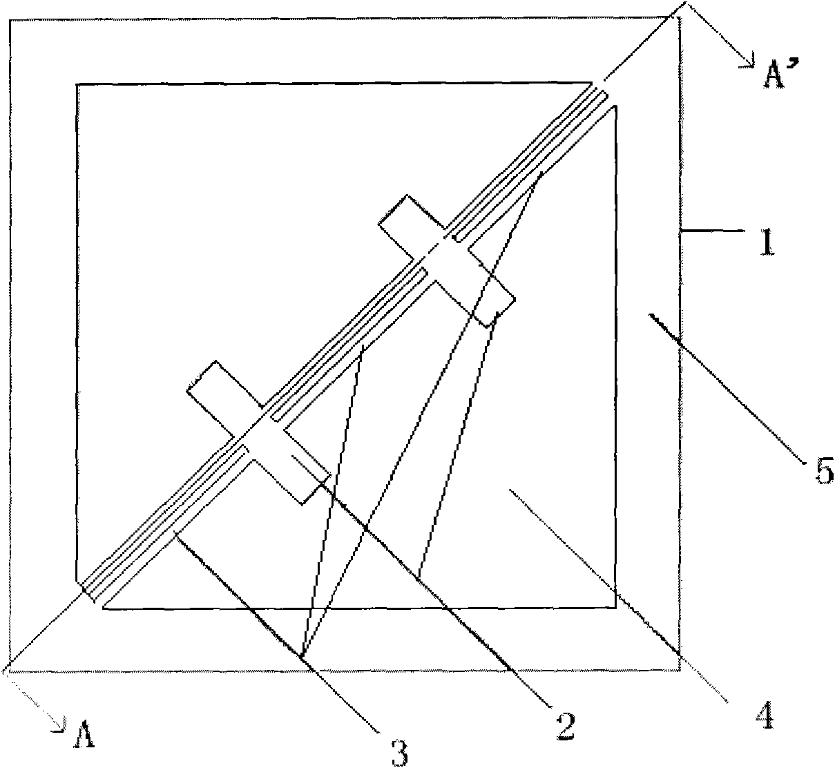
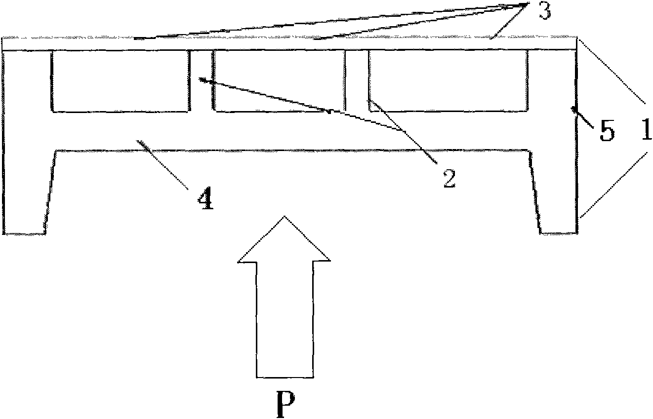
[0044] like figure 1 It is an embodiment of the electromagnetic excitation resonant pressure sensor based on microelectromechanical technology (MEMS) of the present invention, including three groups of the same resonator 3, pressure sensitive film 4, anchor point 2 and frame 5, and the sensor chip adopts MEMS technology in a single fabricated on a crystalline silicon substrate 1.

[0045] The resonator material is boron-rich diffused silicon with insulating dielectric. The insulating dielectric material is silicon nitride or silicon dioxide. Due to the anisotropy shown in the wet etching of single crystal silicon, the three groups of resonators 3 are distributed on the diagonal of the square sensor chip at a diagonal angle of 45°, as shown in figure 1 , so as to facilitate the release of the resonator; the resonator is supported by the anchor point 2 and the frame...


PUM


Abstract

The invention discloses a micromachine-based electromagnetic excitation resonant pressure sensor, and relates to a micromachine sensing technology. The sensor is provided with three groups of resonators which are clamped by anchor points on a pressure membrane, arranged on a diagonal line of a frame, and provided with electrodes. The resonators applied with excitation signals are excited by magnetic field force under the action of an external magnetic field; and when pressure to be tested is present outside, the pressure membrane generates strain, and the strain is transmitted to the resonators through the anchor points to change the rigidity of the resonators, so that the natural frequency of the resonators is changed, and the pressure to be tested outside can be measured by detecting the frequency of output signals of vibration pickup electrodes. The sensor has two packaging modes, and is subjected to stress isolation through a ceramic ring of which the coefficient of thermal expansion is basically same as monocrystalline silicon. The resonators of the sensor work in a horizontal vibration mode; the shift caused by external factors such as temperature and the like is inhibited through differential output, and the sensitivity is improved; and the resonators are released by a heavy boron-diffusion self-stop corrosion technology, a process is simple and the consistency is high.

Description

technical field [0001] The invention belongs to the technical field of micro-mechanical sensing, and relates to an electromagnetic excitation resonant beam type pressure sensor based on micro-electro-mechanical technology (MEMS). Background technique [0002] The resonant beam pressure sensor consists of two parts: the pressure sensitive membrane and the resonant beam. When the external pressure to be measured changes, the pressure sensitive membrane will generate strain, and the strain will be transferred to the resonator, which will change the stiffness of the resonator, thereby changing the frequency of the resonator. , detecting the frequency change of the resonator can obtain the magnitude of the external pressure to be measured. [0003] The microstructure resonant beam pressure sensor made by MEMS technology is mainly made of single crystal silicon and polycrystalline silicon materials so far. The micro-mechanical silicon resonant pressure sensor is mainly used for h...

Claims


Application Information

Patent Timeline
IPC IPC(8): G01L1/10G01L9/00B81B3/00
Inventor 陈德勇史晓晶王军波毋正伟
Owner INST OF ELECTRONICS CHINESE ACAD OF SCI
Why Eureka
Try Eureka