Large-scale pressure carbonization tower

A carbonization tower, a large-scale technology, applied in the field of pressurized carbonization reaction equipment, can solve the problems of small amount of synthetic conversion gas in single tower processing, low production capacity of single tower, restricting enterprise development, etc., to prolong reaction time and crystal growth time, increase gas The liquid contact area and the effect of improving unfavorable factors

Active Publication Date: 2012-04-25
赵祥海
View PDF3 Cites 3 Cited by
  • Summary
  • Abstract
  • Description
  • Claims
  • Application Information

AI Technical Summary

Problems solved by technology

[0006] 3. The reaction of the pressurized carbonization tower is poor, and the medium temperature is generally 60°C, which cannot be further increased
[0008] 5. Take out the solid-liquid ratio is only 25%, take out CNH 3 Not high, only about 85tt, conversion rate is only 65%
[0009] 6. The amount of synthetic conversion gas for single-tower processing is less, the highest is only 600

Method used


Image

  • Large-scale pressure carbonization tower
  • Large-scale pressure carbonization tower
  • Large-scale pressure carbonization tower

Examples


Embodiment 1

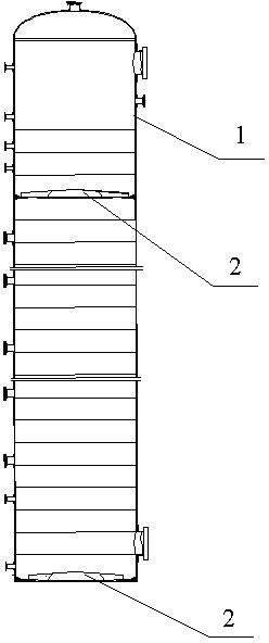
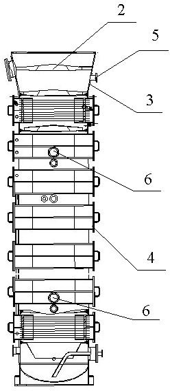
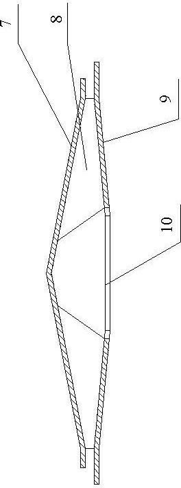
[0030] Embodiment 1, with reference to Figure 1-3 A large-scale pressurized carbonization tower, including an upper tower body 1, a lower water tank 4 and a middle conical tower body 3 connecting the upper tower body 1 and the lower water tank 4, and several sets of hats 2 are respectively arranged in the upper tower body 1 , the lower water tank 4 is provided with several tower sections, and a hat 2 is arranged above each tower section; the hat 2 is composed of a bottom plate 9, a top cover 7 and several ribs 8; the ribs 8 are in the center Symmetrically fixed on the bottom plate 9, the top cover 7 is fixed on the rib plate 8; a through hole 10 is provided in the middle of the bottom plate 9, and the edge of the bottom plate 9 where the through hole 10 is provided is a serrated edge;

[0031] There are 24 sets of hats 2 installed in the tower body 1 of the upper section, among which, the opening rate of the bottom plate 9 of the first to 21st sets of hats 2 from top to botto...

Embodiment 2

[0034] Embodiment 2, in the large pressurized carbonization tower described in Embodiment 1: the bottom plate 9 is in the shape of an inverted cone, and the top cover 7 is in the shape of a cone.

Embodiment 3

[0035] Embodiment 3, in the large-scale pressurized carbonization tower described in embodiment 1: the nominal diameter of the upper tower body 1 is 2700mm; the height of the carbonization tower is 26.4m.


PUM

PropertyMeasurementUnit
Nominal diameteraaaaaaaaaa
Heightaaaaaaaaaa
Nominal diameteraaaaaaaaaa

Abstract

The invention relates to a large-scale pressure carbonization tower which is characterized in that its bamboo rain-hat is composed of a base plate, a top cover and several rib plates; the rib plate is central symmetric and fixed on the base plate; the top cover is fixed on the rib plates; a through hole is arranged at the center of the base plate; the edge of the base plate equipped with the through hole is a zigzag edge; 24 bamboo rain-hats are arranged inside the upper portion of the tower; the opening rate of the first bamboo rain-hat to the 21st bamboo rain-hat from the top to the bottom is 9.8%, and the opening rate of the 22nd bamboo rain-hat to the 24th bamboo rain-hat is 12.8%; one bamboo rain-hat with the opening rate being 13.3% is arranged inside a central conical tower; an airintake is arranged on the central conical tower body; the base plates of the bamboo rain-hats at the bottom are all equipped with appropriate opening rate; and the second and seventh tower sections are respectively provided with two air intakes. According to the invention, ventilation volume and liquid holdup of each portion of the carbonization tower are enlarged; the reaction time and crystal growth time are prolonged; carbonization tower production power and carbonization conversion rate are raised; sodium bicarbonate crystalline particles become large and many unfavorable factors of original carbonization towers are improved.

Description

technical field [0001] The invention relates to a pressurized carbonization reaction equipment for changing gas to produce alkali, in particular to a large pressurized carbonization tower. Background technique [0002] At present, there are roughly three methods for producing soda ash in China, which are ammonia-soda method, combined soda method and trona method. Among them, the key equipment for producing soda ash by combined soda method is the carbonization tower, and the shift gas soda production process mainly includes the following aspects. Firstly, the shift gas in the synthesis shift section enters from the bottom of the pressurized carbonization tower, and contacts and reacts with the neutralized ammonia mother liquor from the top of the carbonization tower. Through this process, the energy, momentum and mass of the substance are fully transferred, and the carbonic acid produced after the reaction Sodium hydrogen high-temperature solution, this high-temperature solut...

Claims


Application Information

Patent Timeline
IPC IPC(8): C01D7/18
Inventor 赵祥海
Owner 赵祥海
Why Eureka
Try Eureka