Sugar liquid evaporator with sharp expansion and accelerated flow converging-diverging tubes inserted with twisted leaves

A swirling sheet and evaporator technology, which is applied in the field of evaporators to enhance heat transfer, can solve the problems of large differences in sugar liquid concentration and viscosity distribution, slow fluid velocity near the wall, low heat transfer coefficient, etc., and achieve strong heat transfer. The effect of field synergy, reducing wall scaling and improving convective heat transfer coefficient

Inactive Publication Date: 2012-05-02
SOUTH CHINA UNIV OF TECH
View PDF3 Cites 2 Cited by
  • Summary
  • Abstract
  • Description
  • Claims
  • Application Information

AI Technical Summary

Problems solved by technology

However, due to the high viscosity of the sugar liquid, the natural convection or forced convection flow boiling evaporation heat transfer operation in the smooth tube evaporator has a very low Reynolds number, and is in the flow state of laminar flow or transition flow. The fluid in the fluid area is difficult to replace each other, and the transfer efficiency of the fluid relying on its own molecular diffusion

Method used


Image

  • Sugar liquid evaporator with sharp expansion and accelerated flow converging-diverging tubes inserted with twisted leaves
  • Sugar liquid evaporator with sharp expansion and accelerated flow converging-diverging tubes inserted with twisted leaves
  • Sugar liquid evaporator with sharp expansion and accelerated flow converging-diverging tubes inserted with twisted leaves

Examples


Embodiment 1

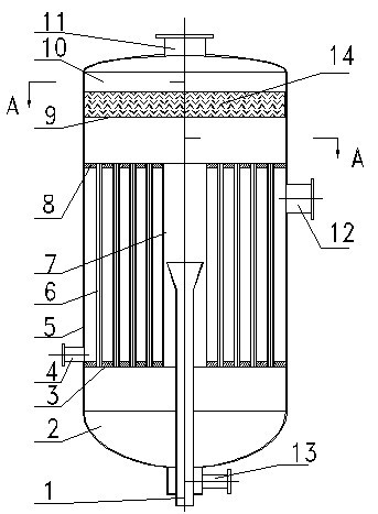
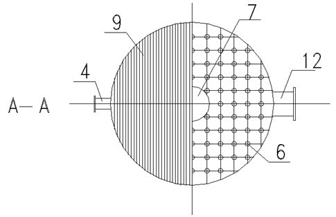
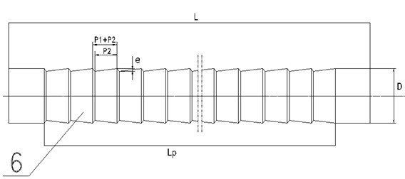
[0029] The structure of the sugar liquid evaporator in this embodiment is as shown above. The cylinder body 5 is made of 304 stainless steel, with a diameter of Φ2000x16mm and a height of 2000mm. There are 1170 internally inserted swirl slice rapid expansion and acceleration flow zoom tubes 6 in the cylinder body 5 (the front view of which is shown in image 3 shown). The tube body is made of 304 stainless steel, the tube length is 2000mm, and the tube diameter D is Φ45x3mm. The ratio of the length P2 of the contraction section to the length P1 of the expansion section is 8:1, and the periodic rib spacing (P1+P2) is 10 times the rib depth e , The rib depth e is 8% of the pipe diameter D, arranged in a square along the cylinder, the pipe spacing is 58mm, the diameter of the downcomer 7 in the axial center area is Φ250x10mm, and the length is 2000mm. The rapid expansion of the inserted swirl sheet and the rapid expansion of the accelerated flow zoom tube 6 and the downcomer 7 a...


PUM

PropertyMeasurementUnit
Angleaaaaaaaaaa
Widthaaaaaaaaaa
Plate thicknessaaaaaaaaaa

Abstract

The invention relates to a sugar liquid evaporator with sharp expansion and accelerated flow converging-diverging tubes inserted with twisted leaves. The sugar liquid evaporator is characterized in that: the sugar liquid evaporator comprises a cylindrical shell, and an upper steam chamber, an upper tube plate, sharp expansion and accelerated flow converging-diverging tubes inserted with twisted leaves, a central downcomer, a lower tube plate and a lower head which are sequentially arranged in the cylindrical shell, wherein the axis of the central downcomer is coincident with the axis of the cylindrical shell; and the bottom of the lower head is provided with a tube side sugar liquid outlet and a tube side sugar liquid inlet, the top of the upper steam chamber is provided with a tube side secondary steam outlet, and a shell side primary steam inlet and a shell side condensed water outlet are arranged on the cylindrical shell between the upper tube plate and the lower tube plate. By utilizing the local intelligent repeated displacement and the disturbance of periodic converging-diverging rib surfaces and the inserted twisted leaves of the converging-diverging tubes to main flows in the tubes and fluids close to walls of the tubes in the sugar liquid evaporator, the sugar liquid evaporator allows the concentration and the viscosity of the sugar liquid which is on a channel section and is obtained by the flow boiling evaporation under natural convection conditions to be uniformly distributed, the convective heat transfer coefficient and the convective diffusion capability of the fluids in the tubes to be substantially improved, a phenomenon that concentration distributions and concentration distributions of the sugar liquid at central fluid parts and at places close to the walls are not uniform to be improved, and the wall area scale of the sugar liquid to be reduced.

Description

technical field [0001] The invention relates to an evaporator for enhanced heat transfer, in particular to a sugar liquid evaporator using a swirl sheet inserted into a rapidly expanding, accelerating-flow zooming tube. Background technique [0002] There are many kinds of evaporator technologies, such as shell-and-tube evaporators, plate evaporators, evaporators using natural convection or forced convection flow boiling, and evaporators using falling film evaporation. The vast majority of evaporators are traditional smooth tube shell-and-tube evaporators, and the heat transfer method is natural convection or forced convection flow boiling evaporation. The advantages of this evaporator are good mechanical sealing and pressure bearing capacity. High, the seal between the cold and hot sides of the tube side and the shell side is only the welding or expansion joint seal between the tubes at both ends of the tube bundle and the tube sheet, so it can be used in high temperature a...

Claims


Application Information

Patent Timeline
IPC IPC(8): B01D1/06B01D1/30
Inventor 邓先和张连山
Owner SOUTH CHINA UNIV OF TECH
Why Eureka
Try Eureka